
Abstract
The influence of crack geometry on the buckling load of axially compressed mild steel cones was presented in this paper. The following geometrical parameter was used: bottom radius-to-top radius ratio, r2/r1=2.0; top radius-to-thickness ratio, r1/t=25; axial length-to-bottom radius ratio, L/r2=2.24; nominal shell thickness, t=1mm; cone angle, β=12.6°. The local buckling phenomenon was investigated through a series of numerical computations (50 ≤ r1/t ≤ 2000). Numerical results show that crack geometry (i.e., length and orientation) influences the buckling strength of the cones differently. For instance, as the crack length increases, the loading capacity of cones drops; cones with a circumferential crack (0°) display the most severe drop. As the crack orientation increases (from 0° to 90°) the buckling strength of the cracked cones with crack length greater than 1 increases. Whereas, for cracked cones with crack length less than 1, increasing the crack orientation has little or no effect on the buckling strength. Hence, it can be said that crack orientation has a secondary effect on the buckling of cracked conical shells.
Keywords
Axial compression; buckling; cracked conical shell; finite element method; mesh-zooming technique
1 INTRODUCTION
Conical shells structures find application in various engineering industries such as offshore, onshore, aircraft, and aeronautical. Real-life applications reveal that this type of structure is often subjected to axial compression (Ifayefunmi and Fadzullah, 2017Ifayefunmi, O., Fadzullah, S.H.S.M. (2017). Buckling behaviour of imperfect axially compressed cylinder with an axial crack, International Journal of Automotive and Mechanical Engineering, 14(1): 3837–3848. https://doi.org/10.15282/ijame.14.1.2017.3.0313.
https://doi.org/10.15282/ijame.14.1.2017...
). The buckling behavior of conical shell is usually deemed as imperfection sensitive. This imperfection includes initial geometric imperfection, uneven length, imperfect boundary conditions, material discontinuity and crack. The presence of defects will impact the buckling strength of the conical shell. However, the imperfection sensitivity of conical shells is significantly influenced by the approach adopted during the introduction of defects on conical shells. Recent reviews on the instability of imperfect conical shells were presented in (Ifayefunmi and Błachut, 2018Ifayefunmi, O., Błachut, J. (2018). Imperfection Sensitivity: A Review of Buckling Behavior of Cones, Cylinders, and Domes, Journal of Pressure Vessel Technology, Transactions of the ASME, 140(5). https://doi.org/10.1115/1.4039695
https://doi.org/10.1115/1.4039695...
; Ifayefunmi, 2014Ifayefunmi, O. (2014). A survey of buckling of conical shells subjected to axial compression and external pressure, Journal of Engineering Science and Technology Review, 7(2), 182–189. https://doi.org/10.25103/jestr.072.27
https://doi.org/10.25103/jestr.072.27...
).
Earlier studies on the buckling behavior of cracked shells were found to be dated back to seventies and eighties (El Naschie, 1974El Naschie, M.S. (1974). A branching solution for the local buckling of a circumferentially cracked cylindrical shell, International Journal of Mechanical Sciences, 16(10): 689–697. https://doi.org/10.1016/0020-7403(74)90095-2
https://doi.org/10.1016/0020-7403(74)900...
; Dyshel, 1989Dyshel, M.S. (1989). Stability of a cracked cylindrical shell in tension, Soviet Applied Mechanics, 25(6): 542–548. https://doi.org/10.1007/BF00887055
https://doi.org/10.1007/BF00887055...
). The problem of cracked cylindrical shell was first addressed in (El Naschie, 1974El Naschie, M.S. (1974). A branching solution for the local buckling of a circumferentially cracked cylindrical shell, International Journal of Mechanical Sciences, 16(10): 689–697. https://doi.org/10.1016/0020-7403(74)90095-2
https://doi.org/10.1016/0020-7403(74)900...
). An overview of various retrofitting methods for preventing cracks in steel structures can be found in (Karamloo, Mazloom and Ghasemi, 2019Karamloo M., Mazloom, M., Ghasemi, A. (2019). An overview of different retrofitting methods for arresting cracks in steel structures, Structural Monitoring and Maintenance, 6(4): 291–315. https://doi.org/10.12989/smm.2019.6.4.291
https://doi.org/10.12989/smm.2019.6.4.29...
). Linear eigenvalue analyses were often adopted in numerical modelling of the buckling behaviour of cylinders having crack imperfection (Jahromi and Vaziri, 2012Jahromi, B.H. and Vaziri, A. (2012). Instability of cylindrical shells with single and multiple cracks under axial compression, Thin-Walled Structures, 54: 35–43. https://doi.org/10.1016/j.tws.2012.01.014
https://doi.org/10.1016/j.tws.2012.01.01...
; Kim, 2011Kim, Y. (2011). Buckling of a cracked cylindrical shell reinforced with an elastic liner, Master’s Dissertation, Northeastern University, Boston, Massachusetts.; Kim et al., 2013Kim, Y.T., Haghpanah, B., Ghosh, R., Ali, H., Hamouda, A.M.S., Vaziri, A. (2013). Instability of a cracked cylindrical shell reinforced by an elastic liner, Thin-Walled Structures, 70: 39-48. https://doi.org/10.1016/j.tws.2013.04.008.
https://doi.org/10.1016/j.tws.2013.04.00...
; Shariati et al., 2010Shariati, M., Sedighi, M., Saemi, J., Eipakchi, H.R., Allahbakhsh, H.R. (2010). Numerical and experimental investigation on ultimate strength of cracked cylindrical shells subjected to combined loading, Mechanika, 84(4): 12–19. https://doi.org/10.5755/j01.mech.84.4.15932
https://doi.org/10.5755/j01.mech.84.4.15...
; Vaziri and Estekanchi, 2006Vaziri, A. and Estekanchi, H.E. (2006). Buckling of cracked cylindrical thin shells under combined internal pressure and axial compression, Thin-Walled Structures, 44(2): 141–151. https://doi.org/10.1016/j.tws.2006.02.004
https://doi.org/10.1016/j.tws.2006.02.00...
). Jahromi and Vaziri (2012)Jahromi, B.H. and Vaziri, A. (2012). Instability of cylindrical shells with single and multiple cracks under axial compression, Thin-Walled Structures, 54: 35–43. https://doi.org/10.1016/j.tws.2012.01.014
https://doi.org/10.1016/j.tws.2012.01.01...
; Kim (2011)Kim, Y. (2011). Buckling of a cracked cylindrical shell reinforced with an elastic liner, Master’s Dissertation, Northeastern University, Boston, Massachusetts.; Kim et al. (2013)Kim, Y.T., Haghpanah, B., Ghosh, R., Ali, H., Hamouda, A.M.S., Vaziri, A. (2013). Instability of a cracked cylindrical shell reinforced by an elastic liner, Thin-Walled Structures, 70: 39-48. https://doi.org/10.1016/j.tws.2013.04.008.
https://doi.org/10.1016/j.tws.2013.04.00...
and Vaziri and Estekanchi (2006)Vaziri, A. and Estekanchi, H.E. (2006). Buckling of cracked cylindrical thin shells under combined internal pressure and axial compression, Thin-Walled Structures, 44(2): 141–151. https://doi.org/10.1016/j.tws.2006.02.004
https://doi.org/10.1016/j.tws.2006.02.00...
were dedicated to aluminium cylinders while steel cylinders were presented in (Shariati et al., 2010Shariati, M., Sedighi, M., Saemi, J., Eipakchi, H.R., Allahbakhsh, H.R. (2010). Numerical and experimental investigation on ultimate strength of cracked cylindrical shells subjected to combined loading, Mechanika, 84(4): 12–19. https://doi.org/10.5755/j01.mech.84.4.15932
https://doi.org/10.5755/j01.mech.84.4.15...
). All of the studies were dedicated to cylinders subjected to axial compression. While, Shariati et al. (2010)Shariati, M., Sedighi, M., Saemi, J., Eipakchi, H.R., Allahbakhsh, H.R. (2010). Numerical and experimental investigation on ultimate strength of cracked cylindrical shells subjected to combined loading, Mechanika, 84(4): 12–19. https://doi.org/10.5755/j01.mech.84.4.15932
https://doi.org/10.5755/j01.mech.84.4.15...
and Vaziri and Estekanchi (2006)Vaziri, A. and Estekanchi, H.E. (2006). Buckling of cracked cylindrical thin shells under combined internal pressure and axial compression, Thin-Walled Structures, 44(2): 141–151. https://doi.org/10.1016/j.tws.2006.02.004
https://doi.org/10.1016/j.tws.2006.02.00...
cover cylinder subjected to combined loading. Ibraheem, Abu Bakar and Johari (2015)Ibraheem, O.F., Abu Bakar, B.H., Johari, I. (2015). Behaviour and crack development of fiber-reinforced concrete spandrel beams under combined loading: an experimental study, Structural Engineering and Mechanics, 54(1): 1–17. https://doi.org/10.12989/sem.2015.54.1.001
https://doi.org/10.12989/sem.2015.54.1.0...
conducted an experimental study on the behavior and crack development on composite concrete beam. An interesting experimental study was presented in (Luo, Ge and Ohashi, 2012Luo X., Ge, H., Ohashi, M. (2012). Experimental study on ductile crack initiation in compact section steel columns, Steel and Composite Sructures, 13(4): 383–396. https://doi.org/10.12989/scs.2012.13.4.383
https://doi.org/10.12989/scs.2012.13.4.3...
) on cracked steel columns with small width-to-thickness ratio. The effect of the presence of crack imperfection on circular steel filled with concrete appeared in (Cui and Shao, 2015Cui, M.J., Shao, Y.B. (2015). Residual static strength of cracked concrete-filled circular steel tubular (CFCST) T-joint, Steel and Composite Structures, 18(4): 1045–1062. https://doi.org/10.12989/scs.2015.18.4.1045
https://doi.org/10.12989/scs.2015.18.4.1...
). The buckling problem for the cracked shell was extended to the conical structure and presented through numerical analysis by Ali, 2013. Additionally, recent experimental studies were carried out on mild steel cylindrical shell (Ifayefunmi, 2016Ifayefunmi, O. (2016). The effect of axial crack on the buckling behavior of axially compressed cylinders, International Journal of Mechanical and Mechatronics Engineering, 16(6): 12–17. retrieved from: http://ijens.org/
http://ijens.org/...
; Ifayefunmi and Fadzullah, 2017Ifayefunmi, O., Fadzullah, S.H.S.M. (2017). Buckling behaviour of imperfect axially compressed cylinder with an axial crack, International Journal of Automotive and Mechanical Engineering, 14(1): 3837–3848. https://doi.org/10.15282/ijame.14.1.2017.3.0313.
https://doi.org/10.15282/ijame.14.1.2017...
), and concrete (Sarfarazi et al., 2018Sarfarazi, V., Haeri, H., Shemirani, A.B., Zhu, Z., Marji, M.F. (2018). Experimental and numerical simulating of the crack separation on the tensile strength of concrete, Structural Engineering and Mechanics, 66(5): 569–582. https://doi.org/10.12989/sem.2018.66.5.569
https://doi.org/10.12989/sem.2018.66.5.5...
). Ifayefunmi, 2016 and Ifayefunmi and Fadzullah, 2017 were limited to the influence of axial crack. The crack length-to-axial length ratio magnitude was varied from 0 to 0.15 in (Ifayefunmi and Fadzullah, 2017Ifayefunmi, O., Fadzullah, S.H.S.M. (2017). Buckling behaviour of imperfect axially compressed cylinder with an axial crack, International Journal of Automotive and Mechanical Engineering, 14(1): 3837–3848. https://doi.org/10.15282/ijame.14.1.2017.3.0313.
https://doi.org/10.15282/ijame.14.1.2017...
) and from 0.05 to 0.50 in (Ifayefunmi, 2016Ifayefunmi, O. (2016). The effect of axial crack on the buckling behavior of axially compressed cylinders, International Journal of Mechanical and Mechatronics Engineering, 16(6): 12–17. retrieved from: http://ijens.org/
http://ijens.org/...
).
Limitation of information on the buckling behavior of conical shells with crack imperfection was revealed in (Ifayefunmi and Błachut, 2018Ifayefunmi, O., Błachut, J. (2018). Imperfection Sensitivity: A Review of Buckling Behavior of Cones, Cylinders, and Domes, Journal of Pressure Vessel Technology, Transactions of the ASME, 140(5). https://doi.org/10.1115/1.4039695
https://doi.org/10.1115/1.4039695...
). In (Ali, 2013Ali, D. (2013). Buckling of cracked conical frusta under axial compression, Research Journal of Recent Sciences, 2(2): 33-39. retrieved from: http://www.isca.in/rjrs/v2i2.php
http://www.isca.in/rjrs/v2i2.php...
), non-linear numerical analysis was employed to investigate the effect of crack geometry (length and orientation) on the buckling of axially compressed steel conical frusta with wall thickness, t = 1 mm, crack length ranging from 10 mm to 30 mm, and the crack angles are 0°, 30°, 60°, and 90°. Experimental results from (Gupta, Sheriff and Velmurugan, 2006Gupta, N.K., Sheriff, N.M., Velmurugan, R. (2006). A study on buckling of thin conical frusta under axial loads, Thin-Walled Structures, 44(9): 986–996. https://doi.org/10.1016/j.tws.2006.08.010
https://doi.org/10.1016/j.tws.2006.08.01...
), was used as a benchmark for numerical results from this study. Results revealed that, at constant crack length, buckling load increases as a result of increasing crack angle. On the contrary, at a constant crack angle, further reduction of buckling strength was observed as the crack length increases. Here, it can be said that cracked conical shells with circumferential crack (0° crack) produce the worst sensitivity to imperfection. This paper intends to present numerical data into the effect of increasing crack length, A, and crack orientation, θ, on the buckling strength of cones subjected to axial loading and it complements the experimental work presented in (Ifayefunmi, 2020Ifayefunmi, O. (2020). Buckling experiments of cracked axially compressed cones, International Journal of Mechanical and Production Engineering Research and Development, 10(3): 5665–5674. https://doi.org/10.24247/ijmperdjun2020539
https://doi.org/10.24247/ijmperdjun20205...
). It is worth mentioning that for simplicity case, the propagation of crack in the material as well as the prediction of crack growth and crack path were not considered in this study.
2 NUMERICAL EXAMPLES – BUCKLING OF CRACKED CYLINDER SUBJECTED TO AXIAL COMPRESSION
The finite element modeling of cracked shells was carried out using the mesh zooming techniques proposed by Estekanchi and Vafai (1999)Estekanchi, H.E., Vafai, A. (1999). On the buckling of cylindrical shells with through cracks under axial load, Thin-Walled Structures, 35(4): 255–274. https://doi.org/10.1016/s0263-8231(99)00028-2
https://doi.org/10.1016/s0263-8231(99)00...
. To do this, first, the crack was created using Solidworks design software according to the intended crack length and crack width. The model was saved as IGS to be imported into ABAQUS later. Refined mesh size was assigned at the crack tip using the local seed mesh function in ABAQUS. To authenticate the appropriateness of the above numerical scheme, preliminary Finite Element (FE) calculations were done to compare the numerical data presented in (Jahromi and Vaziri, 2012Jahromi, B.H. and Vaziri, A. (2012). Instability of cylindrical shells with single and multiple cracks under axial compression, Thin-Walled Structures, 54: 35–43. https://doi.org/10.1016/j.tws.2012.01.014
https://doi.org/10.1016/j.tws.2012.01.01...
) for axially compressed cylinders having circumferential crack. Two imperfect cylindrical shells with circumferential crack having different radius-to-thickness ratios - denoted as cylinder thinness ratio, R/t from (Jahromi and Vaziri, 2012Jahromi, B.H. and Vaziri, A. (2012). Instability of cylindrical shells with single and multiple cracks under axial compression, Thin-Walled Structures, 54: 35–43. https://doi.org/10.1016/j.tws.2012.01.014
https://doi.org/10.1016/j.tws.2012.01.01...
) were chosen. The crack length is kept constant at 40 mm for all cylinders. The geometry of all models were assumed to be: length, L = 2 m, radius, R = 0.2 m. Eigenvalue analysis using Subspace solver was implemented in ABAQUS. The cylindrical shells were modelled as four-node shell element and six degrees of freedom (S4R in ABAQUS element library). The models were axially compressed and the boundary condition for the lower end of the cylinders were set to be: ux = uy = uz = ϕx = ϕy = ϕz = 0 (u ≡ displacements, ϕ ≡ rotations). Similarly, this boundary condition was extended to the upper end of the cylinder except uy ≠ 0. The material used is aluminium and modelled as elastic material with modulus of elasticity, E = 69 GPa and Poisson’s ratio, υ = 0.33. The results obtained from the adaptation of suggested meshing scheme in the current study were benchmarked with the results from (Jahromi and Vaziri, 2012Jahromi, B.H. and Vaziri, A. (2012). Instability of cylindrical shells with single and multiple cracks under axial compression, Thin-Walled Structures, 54: 35–43. https://doi.org/10.1016/j.tws.2012.01.014
https://doi.org/10.1016/j.tws.2012.01.01...
). Figure 1a presents the generated numerical model using the numerical techniques discussed in the paper. Whilst, Figure 1b depicts the buckling shape for the two models with different cylinder thinness ratio, R/t. The corresponding magnitude of the numerical collapse load for two models is given in Table 1. It is apparent from Table 1 that the discrepancy between the numerical results from Jahromi and Vaziri, 2012 and the current numerical prediction is within an acceptable range of ±1%. Thus, it can be said that the suggested meshing technique is appropriate for this analysis. In the subsequent section, this numerical approach will be employed for the buckling analysis of cracked conical shells subjected to axial compression.
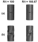
Visualization of (a) undeformed and (b) deformed cylindrical shells having a circumferential crack having different R/t.
Comparison of buckling load of cracked cylindrical shell in referring to (Jahromi and Vaziri, 2012Jahromi, B.H. and Vaziri, A. (2012). Instability of cylindrical shells with single and multiple cracks under axial compression, Thin-Walled Structures, 54: 35–43. https://doi.org/10.1016/j.tws.2012.01.014
https://doi.org/10.1016/j.tws.2012.01.01... ) when subjected to axial compression.
3 BUCKLING OF CRACKED CONICAL SHELLS SUBJECTED TO AXIAL COMPRESSION
In this section, numerical investigations of the buckling behavior of axially compressed cracked conical shells will be presented. Figure 2 shows the conical shell’s geometry with crack imperfection. The geometric parameters of the shell were assumed to be: bottom radius-to-top radius ratio, r2/r1 = 2.0, cone thinness ratio, i.e., top radius-to-thickness ratio, r1/t = 25, axial length-to-bottom radius ratio, L/r2 = 2.24, nominal wall thickness, t = 1 mm and cone angle, β = 12.6º. The conical shells were meshed using the suggested meshing zooming technique discussed in the previous section. Figure 3 depicts the adopted meshing technique applied onto a typical cracked conical shell.


Typical conical shell having 45° crack meshed using suggested meshing technique in the current study with crack length, A = 57 mm.
3.1 Validation of experimental data
Fifteen conical specimens (two perfect and thirteen cracked conical shells) were fabricated from 1 mm mild steel plate and subjected to axial compression as shown in Figure 2. Crack of different orientation, θ, was introduced to the cone and is varied from 0º (circumferential crack), 45º (angular crack) and 90º (longitudinal crack) for several percentages of the crack length-to-axial length of the cone (i.e. 5%, 10%, 15%, 20%, 25% and 50%). The crack is located at the centre of the cone’s meridional surface. Before testing, several measurements of cone thickness, cone diameter, cone length (axial and slant), crack length and crack width were carried out. Then, axial collapse test was carried out on all fifteen specimens using Instron testing machine at the loading rate of 1 mm/min. The top and bottom ends of the specimens were covered with rigid plates to restrict their respective movement during the experiment, hence providing necessary boundary conditions. Figure 4 presents typical experimental setup for this study as exemplified for specimen 1. The material data for the 1 mm mild steel plate obtained via tensile test are as follow: (i) Young’s Modulus, E = 233.30 GPa, (ii) yield stress based on 0.2% offset, σyp = 223.93 MPa, (iii) Poisson’s ratio, υ = 0.3 (taken from the material datasheet). These material properties will be used for the accompanying numerical prediction of the experimental data. Further details of the manufacturing process, pre-test measurements and material testing can be found in (Ifayefunmi, 2020Ifayefunmi, O. (2020). Buckling experiments of cracked axially compressed cones, International Journal of Mechanical and Production Engineering Research and Development, 10(3): 5665–5674. https://doi.org/10.24247/ijmperdjun2020539
https://doi.org/10.24247/ijmperdjun20205...
). Experimental results for fifteen axially compressed perfect and cracked conical shells can be found in column 6 of Table 2.

Buckling load of the cracked conical shell- comparison of experimental (Exptl) and numerical (ABAQUS) results.
First, benchmark of experimental results presented was carried out. Numerical modelling of perfect and cracked conical shells was executed. The conical model was generated as 3D deformable body with four noded shell elements having six degrees of freedom - S4R in ABAQUS, which is suitable for modelling thin-walled shells. Additionally, a rigid plate was created and assembled with the model to maintain the top plate used during the experimental test. The crack imperfection on conical shells was designed as a rectangular hole with fixed crack width (0.01 mm) and a variation of crack length ranging from 5.6 mm to 56 mm using Solidworks prior to numerical computation in ABAQUS. The interaction between the top nodes of the conical shell and the inner side of the rigid plate was defined as surface-to-surface contact. It was assumed to have a frictionless tangential behaviour. Non-linear static analysis was executed by adopting the static Riks loading scheme to obtain the load-displacement curve. The large radius end of the model was considered to be fixed. Similar boundary condition was implemented at the small radius end of the model except allowing it to move in the axial direction. The material used is steel and modelled as elastic perfectly plastic with Young’s modulus, E = 233.3 GPa, yield stress, σy = 223.9 MPa and Poisson’s ratio, υ = 0.3. The comparison between experimental and FE predictions in the buckling behaviour of cones with crack imperfection is explored. Table 2 presents the comparison between experimental results and the corresponding FE predictions.
Contrary to (Ali, 2013Ali, D. (2013). Buckling of cracked conical frusta under axial compression, Research Journal of Recent Sciences, 2(2): 33-39. retrieved from: http://www.isca.in/rjrs/v2i2.php
http://www.isca.in/rjrs/v2i2.php...
), results indicate that the introduction of 0° crack with a crack percentage of 5% on a conical shell did not reduce its load-carrying capacity from the average buckling load of perfect conical shells. The numerical prediction exhibited a satisfactory agreement with the collapse load from experiment testing. The highest percentage of error between numerical prediction and the experimental result is 18% for specimen 11. Again, the conical samples with circumferential crack imperfection showed the most effect on the reduction of buckling strength. Comparison of the plot of experimental and numerical collapse load against crack percentages for imperfect conical shells having axial crack imperfection is depicted in Figure 5. Similar plots for other crack orientation (i.e., circumferential and angular) can be found in Figure 6 and Figure 7, respectively. All numerical predictions underestimated the experimental results except for cones with 50% angular and longitudinal crack.

Experimental and FE predicted axial load against crack percentage for imperfect conical shells with axial crack.

Experimental and FE predicted axial load against crack percentage for imperfect conical shells with circumferential crack.

Experimental and FE predicted axial load against crack percentage for imperfect conical shells with angular crack.
3.2 Further numerical computations
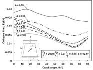
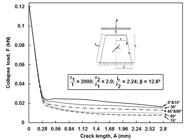
Further numerical computations were carried out on cracked conical shells. Relatively small crack length typically encountered in practise was considered. And the influence of (i) crack orientation, θ, (ii) crack length, A, and (iii) radius-to-thickness ratio (r1/t) on the buckling load of the conical shells were explored. The crack length, A, is varied from 0.28 mm to 1.68 mm and the crack orientation, θ gradually increases from 0° to 90° (where θ = 0° corresponds to circumferential direction as measured from the cone circumferential line). The thinness ratio, r1/t, considered here are 25, 250 and 2000. It is important to note here that for cones with r1/t = 2000, linear buckling analysis was carried out, while for cones with r1/t = 25 and 250, non-linear static Riks analysis was employed. Table 3 summarizes the collapse load for cones with nominal wall thickness, t = 1 mm for imperfect conical shells having different crack lengths and orientations. Table 3 shows that the buckling strength of imperfect cones drops about 6.57% as the crack length increases from 0.28 mm to 1.68 mm at a constant crack orientation of 0°. Figure 8 shows the plot of collapse load against crack orientation having different crack lengths for cracked cone with thinness ratio, r1/t = 25. Based on Figure 8, it was evident that the increasing crack length resulted in the reduction of the buckling strength of conical shells. Similar results were observed for cracked cones with thinness ratio, r1/t = 250 as in (Figure 9) and r1/t = 2000 as evident in (Figure 10). Generally, it can be said that the buckling loads of conical shell subjected to axial compression with crack imperfection is strongly dependent on the crack length. It is worth mentioning that these results are similar to the ones discussed in the previous literature (Ali, 2013Ali, D. (2013). Buckling of cracked conical frusta under axial compression, Research Journal of Recent Sciences, 2(2): 33-39. retrieved from: http://www.isca.in/rjrs/v2i2.php
http://www.isca.in/rjrs/v2i2.php...
) for cones and (Jahromi and Vaziri, 2012Jahromi, B.H. and Vaziri, A. (2012). Instability of cylindrical shells with single and multiple cracks under axial compression, Thin-Walled Structures, 54: 35–43. https://doi.org/10.1016/j.tws.2012.01.014
https://doi.org/10.1016/j.tws.2012.01.01...
; Kim et al., 2013Kim, Y.T., Haghpanah, B., Ghosh, R., Ali, H., Hamouda, A.M.S., Vaziri, A. (2013). Instability of a cracked cylindrical shell reinforced by an elastic liner, Thin-Walled Structures, 70: 39-48. https://doi.org/10.1016/j.tws.2013.04.008.
https://doi.org/10.1016/j.tws.2013.04.00...
; Shariati et al., 2010Shariati, M., Sedighi, M., Saemi, J., Eipakchi, H.R., Allahbakhsh, H.R. (2010). Numerical and experimental investigation on ultimate strength of cracked cylindrical shells subjected to combined loading, Mechanika, 84(4): 12–19. https://doi.org/10.5755/j01.mech.84.4.15932
https://doi.org/10.5755/j01.mech.84.4.15...
; Vaziri and Estekanchi, 2006Vaziri, A. and Estekanchi, H.E. (2006). Buckling of cracked cylindrical thin shells under combined internal pressure and axial compression, Thin-Walled Structures, 44(2): 141–151. https://doi.org/10.1016/j.tws.2006.02.004
https://doi.org/10.1016/j.tws.2006.02.00...
) for cylinders. Again, as observed in Figures 8 - 10, depending on the thinness ratio, different crack orientation will produce different sensitivity for the conical shells.
Buckling load (kN) of axially compressed conical shells with a variation of crack length and crack angle.

Graph of axial collapse load against crack angle, θ, for cone with thinness ratio, r1/t = 25, having different crack length, A.

Graph of axial collapse load against crack angle, θ, for cone with thinness ratio, r1/t = 250, having different crack length, A.
Graph of axial collapse load against crack angle, θ, for cone with thinness ratio, r1/t = 2000, having different crack length, A.
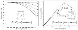
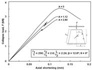
Then, the influence of crack orientation on the load carrying capacity of conical shells having different thinness ratios was considered. Figure 11 shows the plot of collapse load against crack length having different crack orientations for cones with thinness ratio of 25. From Figure 11, it was observed that crack orientation has a secondary effect in the reduction of the buckling load of conical shells having a crack length less than 1 mm, where the changes between buckling strength for different crack angles remain insignificant. Whilst, for imperfect conical shells with crack length greater than 1 mm, increasing the crack orientation results in an increase in the buckling load of the conical shells. Apparently, cracked conical shells with circumferential crack are seen to produce the most severe imperfections – as seen for several crack orientations (i.e., 0°, 30°, 60°, 90°) presented in Figure 12 of (Ali, 2013Ali, D. (2013). Buckling of cracked conical frusta under axial compression, Research Journal of Recent Sciences, 2(2): 33-39. retrieved from: http://www.isca.in/rjrs/v2i2.php
http://www.isca.in/rjrs/v2i2.php...
). For conical shells with thinness ratio of 250, circumferential crack was also seen to produce the worst sensitivity as depicted in Figure 12. However, the effect of crack orientation at small crack length i.e., A < 1, is seen to be more significant as compared to cone with thinness ratio of 25. The same observation can be drawn. This result seems to be in line with the report of Ali (2013)Ali, D. (2013). Buckling of cracked conical frusta under axial compression, Research Journal of Recent Sciences, 2(2): 33-39. retrieved from: http://www.isca.in/rjrs/v2i2.php
http://www.isca.in/rjrs/v2i2.php...
where circumferential crack produces the worst imperfection sensitivity of steel frusta having bottom radius-to-thickness ratio, R/t of 25. Surprisingly, for cracked cones with thinness ratio, r1/t = 2000, this behavior is somewhat different with 75° angled crack producing the worst imperfection as presented in Figure 13. Again, contrary to Figures 11 and 12, for cones with large thinness ratio, the maximum drop in the buckling load can be seen at a very small crack length, A ≤ 0.28. It can be inferred at this point that for crack cones with small thinness ratio, where the failure is governed by collapse, the worst crack orientation is circumferential crack (0°). Whilst, for cracked cones with large radius-to-thickness ratio, where the failure is governed by bifurcation buckling, 75° angled crack is seen to be the most severe imperfection case. This implies that the cone geometry, such as thinness ratio has an influence on the imperfection sensitivity of such structures.

Graph of axial collapse load against crack length, A, for cone with thinness ratio, r1/t = 25, having different crack angle, θ.
Graph of axial collapse load against crack length, A, for cone with thinness ratio, r1/t = 250, having different crack angle, θ.
Graph of axial collapse load against crack length, A, for cone with thinness ratio, r1/t = 2000, having different crack angle, θ.
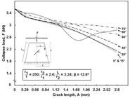
Next, from the foregoing results, it was decided to evaluate the influence of thinness ratio, r1/t, ranging from 25 to 2000 on the buckling behavior of axially compressed cracked conical shells. Figure 14 presents the plot of normalized force against crack length for cracked cone with circumferential crack (0°). A similar plot for cracked conical shells with angled crack (75°) is depicted in Figure 15. It is apparent from both Figures that as the cone thinness ratio increases, its load carrying capacity reduces. It is worth mentioning here that the force is normalized by the collapse load for perfect shell for corresponding thinness ratio (i.e., F/). Figure 16 presents the plot of collapse load versus their corresponding axial shortening for conical shell with thinness ratio of 25 having circumferential crack imperfection - Points 1, 2-A and 3-A on Figure 14.

Graph of normalized axial collapse load versus crack length, A, for cracked cones with circumferential crack (0°) having different radius-thickness ratio, r1/t.

Graph of normalized axial collapse load versus crack length, A, for cracked cones with angled crack (75°) having different radius-thickness ratio, r1/t.

Graph of axial collapse load against axial shortening for perfect and imperfect cone with thinness ratio, r1/t = 25 having circumferential crack.
Similar plots for cone with thinness ratio of 250 - Points 1, 2-B and 3-B on Figure 14, is given in Figure 17. From Figure 16, the load-deflection curve is linear up until collapse loads and in the post-collapse region, a smooth fall of the load-deflection curve is observed for both the perfect and imperfect cones. Whereas for Figure 17, local buckling preceding global buckling can be seen in the plot for imperfect conical shells. This phenomenon is expected and supported by findings in multiple literatures (Jahromi and Vaziri, 2012Jahromi, B.H. and Vaziri, A. (2012). Instability of cylindrical shells with single and multiple cracks under axial compression, Thin-Walled Structures, 54: 35–43. https://doi.org/10.1016/j.tws.2012.01.014
https://doi.org/10.1016/j.tws.2012.01.01...
; Shariati et al., 2010Shariati, M., Sedighi, M., Saemi, J., Eipakchi, H.R., Allahbakhsh, H.R. (2010). Numerical and experimental investigation on ultimate strength of cracked cylindrical shells subjected to combined loading, Mechanika, 84(4): 12–19. https://doi.org/10.5755/j01.mech.84.4.15932
https://doi.org/10.5755/j01.mech.84.4.15...
) where it was stated that at a certain thinness ratio, local buckling is seen first before global buckling occurs. Finally, it was decided to examine the thinness ratio at which cracked cones begin to exhibit local buckling prior to global buckling.
Graph of axial collapse load against axial shortening for perfect and imperfect cone with thinness ratio, r1/t = 250 having circumferential crack.
Figures 18a, b, c and d depict the plots of collapse load versus axial shortening for cracked cones having thinness ratio of 50, 100, 150 and 200, respectively. It can be seen that cracked cones begin to develop local buckling before the occurrence of global buckling at cone thinness ratio, r1/t = 200. From here, it can be said that for axially compressed crack cones with thinness ratio, r1/t < 200, there is no local instability prior to the global buckling. However, this may not be generally true for other cone semi-vertex angles. Hence, a further numerical investigation on different cone angle (β) is hereby advised.
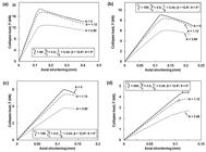
Graph of axial collapse load deformation curve for perfect and imperfect cone with different thinness ratio having circumferential crack.
4 CONCLUSION
This paper presents numerical studies on the buckling behaviour of conical shells having crack imperfection of several crack geometries (length and orientation) subjected to axial loading. The benchmark of previous work on cylinders using the proposed mesh zooming techniques was very good. Hence confirming the appropriateness of the proposed meshing scheme adopted in the paper. The following conclusions can be made from the preceding results:
-
1
Increasing the crack length of the cones results in decreased conical shell buckling load.
-
2
The effect of crack orientation is minimal for small crack length for cones with small thinness ratio, and as the thinness ratio increases, this effect becomes increasingly significant. Again, it is evident that the most severe crack orientation is strongly dependent on the thinness ratio. For cones with low thinness ratio characterized by collapse failure, circumferential crack produces the worst imperfection. Whereas, for cones with large thinness ratio, where the failure is controlled by bifurcation buckling, 75° angled crack is the worst.
-
3
At a certain thinness ratio, i.e. r1/t ≥ 200, the cracked cone develops local instability prior to global buckling. This is true for the cone angle (β = 12.6°) considered in this paper.
Acknowledgment
The authors would like to express gratitude to Mr Muhammad Zulfirdaus Zulkafle for his help during the experiment and Universiti Teknikal Malaysia Melaka (UTeM) in conjunction with the Ministry of Education Malaysia under the Fundamental Research Grant Scheme FRGS/2018/FTKMP-CARE/F00386 for their financial assistance.
References
- Ali, D. (2013). Buckling of cracked conical frusta under axial compression, Research Journal of Recent Sciences, 2(2): 33-39. retrieved from: http://www.isca.in/rjrs/v2i2.php
» http://www.isca.in/rjrs/v2i2.php - Cui, M.J., Shao, Y.B. (2015). Residual static strength of cracked concrete-filled circular steel tubular (CFCST) T-joint, Steel and Composite Structures, 18(4): 1045–1062. https://doi.org/10.12989/scs.2015.18.4.1045
» https://doi.org/10.12989/scs.2015.18.4.1045 - Dyshel, M.S. (1989). Stability of a cracked cylindrical shell in tension, Soviet Applied Mechanics, 25(6): 542–548. https://doi.org/10.1007/BF00887055
» https://doi.org/10.1007/BF00887055 - Estekanchi, H.E., Vafai, A. (1999). On the buckling of cylindrical shells with through cracks under axial load, Thin-Walled Structures, 35(4): 255–274. https://doi.org/10.1016/s0263-8231(99)00028-2
» https://doi.org/10.1016/s0263-8231(99)00028-2 - El Naschie, M.S. (1974). A branching solution for the local buckling of a circumferentially cracked cylindrical shell, International Journal of Mechanical Sciences, 16(10): 689–697. https://doi.org/10.1016/0020-7403(74)90095-2
» https://doi.org/10.1016/0020-7403(74)90095-2 - Gupta, N.K., Sheriff, N.M., Velmurugan, R. (2006). A study on buckling of thin conical frusta under axial loads, Thin-Walled Structures, 44(9): 986–996. https://doi.org/10.1016/j.tws.2006.08.010
» https://doi.org/10.1016/j.tws.2006.08.010 - Ibraheem, O.F., Abu Bakar, B.H., Johari, I. (2015). Behaviour and crack development of fiber-reinforced concrete spandrel beams under combined loading: an experimental study, Structural Engineering and Mechanics, 54(1): 1–17. https://doi.org/10.12989/sem.2015.54.1.001
» https://doi.org/10.12989/sem.2015.54.1.001 - Ifayefunmi, O. (2014). A survey of buckling of conical shells subjected to axial compression and external pressure, Journal of Engineering Science and Technology Review, 7(2), 182–189. https://doi.org/10.25103/jestr.072.27
» https://doi.org/10.25103/jestr.072.27 - Ifayefunmi, O. (2016). The effect of axial crack on the buckling behavior of axially compressed cylinders, International Journal of Mechanical and Mechatronics Engineering, 16(6): 12–17. retrieved from: http://ijens.org/
» http://ijens.org/ - Ifayefunmi, O. (2020). Buckling experiments of cracked axially compressed cones, International Journal of Mechanical and Production Engineering Research and Development, 10(3): 5665–5674. https://doi.org/10.24247/ijmperdjun2020539
» https://doi.org/10.24247/ijmperdjun2020539 - Ifayefunmi, O., Błachut, J. (2018). Imperfection Sensitivity: A Review of Buckling Behavior of Cones, Cylinders, and Domes, Journal of Pressure Vessel Technology, Transactions of the ASME, 140(5). https://doi.org/10.1115/1.4039695
» https://doi.org/10.1115/1.4039695 - Ifayefunmi, O., Fadzullah, S.H.S.M. (2017). Buckling behaviour of imperfect axially compressed cylinder with an axial crack, International Journal of Automotive and Mechanical Engineering, 14(1): 3837–3848. https://doi.org/10.15282/ijame.14.1.2017.3.0313.
» https://doi.org/10.15282/ijame.14.1.2017.3.0313 - Jahromi, B.H. and Vaziri, A. (2012). Instability of cylindrical shells with single and multiple cracks under axial compression, Thin-Walled Structures, 54: 35–43. https://doi.org/10.1016/j.tws.2012.01.014
» https://doi.org/10.1016/j.tws.2012.01.014 - Karamloo M., Mazloom, M., Ghasemi, A. (2019). An overview of different retrofitting methods for arresting cracks in steel structures, Structural Monitoring and Maintenance, 6(4): 291–315. https://doi.org/10.12989/smm.2019.6.4.291
» https://doi.org/10.12989/smm.2019.6.4.291 - Kim, Y. (2011). Buckling of a cracked cylindrical shell reinforced with an elastic liner, Master’s Dissertation, Northeastern University, Boston, Massachusetts.
- Kim, Y.T., Haghpanah, B., Ghosh, R., Ali, H., Hamouda, A.M.S., Vaziri, A. (2013). Instability of a cracked cylindrical shell reinforced by an elastic liner, Thin-Walled Structures, 70: 39-48. https://doi.org/10.1016/j.tws.2013.04.008.
» https://doi.org/10.1016/j.tws.2013.04.008 - Luo X., Ge, H., Ohashi, M. (2012). Experimental study on ductile crack initiation in compact section steel columns, Steel and Composite Sructures, 13(4): 383–396. https://doi.org/10.12989/scs.2012.13.4.383
» https://doi.org/10.12989/scs.2012.13.4.383 - Sarfarazi, V., Haeri, H., Shemirani, A.B., Zhu, Z., Marji, M.F. (2018). Experimental and numerical simulating of the crack separation on the tensile strength of concrete, Structural Engineering and Mechanics, 66(5): 569–582. https://doi.org/10.12989/sem.2018.66.5.569
» https://doi.org/10.12989/sem.2018.66.5.569 - Shariati, M., Sedighi, M., Saemi, J., Eipakchi, H.R., Allahbakhsh, H.R. (2010). Numerical and experimental investigation on ultimate strength of cracked cylindrical shells subjected to combined loading, Mechanika, 84(4): 12–19. https://doi.org/10.5755/j01.mech.84.4.15932
» https://doi.org/10.5755/j01.mech.84.4.15932 - Vaziri, A. and Estekanchi, H.E. (2006). Buckling of cracked cylindrical thin shells under combined internal pressure and axial compression, Thin-Walled Structures, 44(2): 141–151. https://doi.org/10.1016/j.tws.2006.02.004
» https://doi.org/10.1016/j.tws.2006.02.004
Edited by
Publication Dates
-
Publication in this collection
11 Dec 2020 -
Date of issue
2020
History
-
Received
26 Aug 2020 -
Accepted
29 Oct 2020


