
Abstract
Tower structures are sensitive to hurricanes or earthquakes, whereupon they are easily damaged due to large deflection and dynamic responses. Herein, a method is proposed to accurately identify the location and extent of damage in tower structures. Firstly, a tower structure is divided into several sections along its height, and each section is regarded as a super element. Based on the finite element method (FEM), the displacement, mass, and stiffness matrices of a super element are constructed to establish the free motion equation of tower structures. Secondly, the stiffness of each component of the tower structure is included in a coefficient as the damage parameter. The first-order partial derivative of the frequencies and mode shapes of the structure for the damage parameters is obtained through Taylor expansion to construct overdetermined linear equations with the damage parameters as unknown. The values of the damage parameters can be obtained by solving the equations, and the locations and extent of damages of the structure can be obtained according to the number and values of the parameters. Furthermore, to greatly improve the accuracy of the damage identification, the modification of modal truncation error is proposed. Finally, the numerical simulation of a 12-story steel TV tower verifies the feasibility and effectiveness of the proposed method.
Keywords:
damage detection; tower structures; super elements; dynamic parameters; modal truncation error
1. Introduction
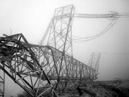
Tower structures are a type of slender and lofty structures, whose altitude is much greater than its width, often by a significant margin. Since the cross section of tower structures is a relatively small lateral load, it plays an important role in the structural dynamic responses [Haoxiang, He Xin Xie, and Wentao Wang, 2017HE, H.; XIE, X.; WANG, W. Vibration control of tower structure with multiple cardan gyroscopes. Shock and Vibration , v. 2017, p. 1-11, 2017.]. Because of the tall and beautiful form of tower structures, they are widely used in the field as communication facilities, power facilities, as well as in chemical engineering, and so forth. Compared with other common building structures, tower structures have weak horizontal stiffness, so they are sensitive to hurricanes and earthquakes, and prone to generate large static deflection and even damage. Fig.1 shows the wind-induced collapse accident of the 5237 liner with 500 kV transmission tower, and 10 transmission towers were broken once in Jiangsu, China. Therefore, the research on damage diagnosis of tower structures has received increasing attention.
Hui Hou et al. [2019HOU, H.; GENG, H.; HUANG, Y.; WU, H.; WU, X.; YU, S. Damage probability assessment of transmission line-tower system under typhoon disaster, based on model-driven and data-driven views. Energies , v. 12, n. 8, p. 1-17, 2019.] proposed an assessment method for damage probability of a transmission line-tower system suffering typhoons. Taking into account the difference between actual and in-design wind loads, they established a physical model to calculate the damage probability of the transmission line and power tower. And then, the damage probability of the system was obtained by being combined with the above two parts. However, this method cannot determine the location and extent of damages. Zhou Ling et al. [2016LING, Z.; YING-TAO, L.; CHAO-SHAN, Y.; ZHI-PING, D.; JIN, C. Research on dynamic similarity model test of damage detection for transmission tower. The Civil Engineering Journal , v. 3, p. 1-9, 2016.] forwarded a new damage detection index with clear physical signification for the damage detection of transmission towers. They carried out a damage detection test on an elastic model of a transmission tower with 1/35 scale, and the results showed that the proposed index is feasible and effective. Hermes Carvalho et al. [2016CARVALHO, H.; QUEIROZ, G.; FAKURY, R. H. Experimental evaluation of the wind effects on an operating power transmission tower. Mechanic and Energy , v. 69, n. 3, p. 325-331, 2016.] experimented on a suspension tower of a 138kV transmission line in use and verified that the geometric nonlinear has a great influence on transmission towers. Zhuoqun Zhang et al. [2013ZHANG, Z.; LI, H.; LI, G.; WANG, W.; TIAN, L. The numerical analysis of transmission tower-line system wind-induced collapsed performance. Mathematical Problems in Engineering , v. 2013, p. 1-11, 2013.] established two finite element models for the single tower and tower-line system to simulate the wind-induced progressive collapse with the birth-to-death element technique in ABAQUS /Explicit. The numerical simulation results demonstrated that the collapse mechanism of the transmission tower-line system depended on the number, position, and last deformation of damaged elements.
Due to numerous components of tower structures, improving calculation efficiency plays an important role in analyzing them. The super element method (SEMD) largely reduces degrees of freedom and greatly improves calculation efficiency [Ma Hongliang, Jia Haitao and Liu Wei, 2009MA, H.; JIA, H.; LIU, W; WU, Q. A Study of the key problem in the application of super element. Computer Simulation , v. 26, n. 5, p. 48-51, 2009.]. Liu et al. [1995] applied SEMD to complicated special frame structures for the first time. Their work indicates that it is a very practical and effective method with few degrees of freedom and much less computational work. Cao et al. [2000CAO, Z.; FU, Z. Super element method for the destruction and collapse analyses of complicated systems. Journal of Tongji University , v.28, n. 3, p. 253-256, 2000. ] used SEMD to successfully perform nonlinear analysis of complex structures. A new super-element with twelve degrees of freedom to be used in finite element modeling of latticed columns was presented by A. Fooladi et al. [2015FOOLADI, A.; BANAN, M. R. A super-element based on finite element method for latticed columns. International Journal of Civil Engineering , v. 13, n. 2, p. 202-212, 2015.]. To show the calculation accuracy of the super-element, they performed both linear and nonlinear analysis on a three-dimensional frame. The outcome revealed that the currently practiced model for latticed columns suffers from some major shortcomings that are resolved to some extent by the proposed super-element. M.P. Galanin et al. [2014GALANIN, M. P.; LAZAREVA, S. A. The finite super element method and its application for solving Science and technology problems. Mathematical Models and Computer Simulations , v. 6, n. 1, p. 19-24, 2014.] presented different variants of SEMD for the simulation of media with small inclusions and implemented the algorithm for the construction of SEMD. A numerical method for determining the characteristics of arbitrary super elements was developed by Alexander Tsybenko et al. [2012]. They built simulation models with two-node super elements and demonstrated the efficacy of the method in the structural analysis of elastic systems. Cao Zhiyuan et al. [1994] applied SEMD to the computation of a tower structure with sixteen layers, and compared the calculation results of SEMD with FEM. The results of their work showed that SEMD was more effective.
As can be seen from the above, although many scholars have studied and analyzed the damage of tower structures from many aspects, they cannot determine the location and degree of the damage, which is the greatest concerned. SEMD is widely used in the analysis of complex structures with its high computational efficiency. Based on the two aspects, a method is proposed to identify damages of tower structures in the article, which not only accurately diagnose the damage location of the structures, but also precisely determine the degree of damage. The idea is: Firstly, a tower structure is divided into several sections along its height, and each section is regarded as a super element with eight nodes. Based on FEM, the free motion equation of the tower structure is established. Secondly, the damage of the tower structure will inevitably cause a change in the stiffness of each component, so the stiffness of each component is included in a coefficient as the damage parameter. And then, the frequency and mode of the structure are regarded as a function of the damage parameters, and the first-order partial derivative of the frequency and mode to the damage parameters is obtained through Taylor expansion. Finally, the overdetermined linear equations with the damage parameters as unknown is constructed, which is solved to obtain the values of the damage parameters. If the value of the damage parameter is not zero, the corresponding component is the damaged one, otherwise, it is undamaged, that is, by querying the number of damaged components and the values of their damage parameters, you can know the location and degree of damages for the entire structure. When constructing the equations, only the first few modes and frequencies of the structure are used, so there is a mode truncation error. In order to improve the accuracy of damage identification, a model error correction technique is proposed. Numerical simulation of a 12-layer steel TV tower verifies the effectiveness and feasibility of the proposed method.
2. Super elements
Tower structures are characterized in that their component members are rods that only bear axial forces, whose height is much larger than their width. Therefore, we can divide one tower structure into several segments along its height, and a segment represents a super element.
2.1 Displacement modes of super element
A spatial 8-node element is adopted as a super element, see Fig.2.

For the super element, there are four deformations in the plane such as tensile deformation, bending deformation, shear deformation and torsional deformation, whereby four independent variables along the axis x are taken as follows [Cao Zhiyuan, Liu Yongren and Zhou Hanbin, 1994CAO, Z.; LIU, Y.; ZHOU, H. Super finite element method and its application in structural engineering analysis. Computational Structural Mechanics and Applications , v. 11, n. 4, p. 454-460, 1994.; Cao Zhiyuan and Fu Zhiping, 2000CAO, Z.; FU, Z. Super element method for the destruction and collapse analyses of complicated systems. Journal of Tongji University , v.28, n. 3, p. 253-256, 2000. ; Liu Yongren, Chao Zhiyuan, 1995YONGREN, L.; ZHIYUAN, C. The static analysis of special frames in architectural structures by the use of super-element method. Shang Hai Journal of Mechanics , v. 16, n. 4, p. 282-289, 1995.].
where uk, wk , φk and θk are the displacements of the k th node; Nk are the interpolation functions, which can be calculated by the following equations [Wang Xucheng, 2003CHENG, W. X. Finite Element Method [M] . Beijing: Tsinghua University Press, 2003. 120p.].
where xk, yk and zk are the coordinate values of the k th node. Eq. (1) can also be expressed in matrix form as
where I4 is a fourth-order unit matrix.
2.2 Finite element analysis of components
When analyzed by the finite element method, every component of the tower structure is treated as a rod with three degrees of freedom at each end. The node displacement vector of the component ij is
The stiffness matrix and mass matrix of the component ij are
>
where [Bb], [Db] and [Nb] are the strain matrix, elastic matrix and shape function matrix, respectively.
2.3 Conversion of operational matrix for rod elements
The node displacements of the component can be also expressed
The values in the global coordinate system of the node i and j are (xi yizi) and (xj yj zj)and , respectively. From Eq. (7), the displacements of the node i and j can be expressed by the displacements of the eight nodes of the super-element
where [E]b is the transformation matrix. The stiffness matrix and mass matrix of the component ij are respectively
where [Kb]e and [Mb]e are all thirty-second order matrixes.
2.4 The stiffness matrix and mass matrix of the super element
According to the variation principle, the stiffness matrix and mass matrix of the super element are formed by simply superposing the corresponding operation matrices of all its components
3. Basic equations of damage diagnose
When the damage parameters regarded as the stiffness coefficients of each rod, the tensile-compressive stiffness of the i th component of the j th super element is
where Dij is the damage parameter of the i th component of the j th super element and used to describe the damage severity. The range of its values is from 1 to 0, when Dij is equal to 0, it means that the component is intact; when Dij is equal to 1, it means that the component is completely damaged. The larger the value of Dij , the more serious the damage. EA is the tensile-compressive stiffness of the undamaged rod.
The elastic behavior of a system can be expressed either in terms of the stiffness or the flexibility. We write the equations of motion for the normal mode vibration in terms of the stiffness:
where M and Kd are the mass and stiffness matrix of the damaged structure, respectively. We assume that damage is not accompanied by a change in the mass matrix; U is the n -dimension displacement vector. The general solution to Eq. (12) is , where θ and ω are the amplitude vector and the natural frequency, respectively. Substituting into Eq. (12) gives
where ωr and θ Φ are the rth natural frequency and mode shape, respectively. The following equation defines the orthogonal character of the normal modes
where . With the frequency ωr being regarded as the function of the damage parameter Dij, the function is expanded as the Tailor series given by
where ωr0 is rth th natural frequency of the intact structure, p is the number of components of the jth super element, and q is the number of super elements. With the item including the first power of Dij in Eq. (15) being only reserved, the difference of frequency between the damaged structure and the intact is:
where ∂ωr/∂Dij is the constant term and solved later, and N is the total number of components. In the same way, the difference of mode shape of the damaged structure and the intact can be obtained
where ∂Φr /¶Dij is the constant term too and solved later. Due to the incomplete measurement, only the first n-order mode shape can be taken (n ≤ N). When r changes from 1 to n, the linear equations for damage parameters as unknowns can be constructed. The whole damage parameters can be found by solving the following algebraic equations, that is, the damaged components are identified.
where Δ = {Δω1,L , Δϕ11,L , Δϕn1,L , Δϕ1n ,L , Δϕnn} is the array of difference of both frequency and mode shape; D = { D11,L , Dij ,L , Dpq}T is the array of damage parameters to be sought; S is the matrix of first-order partial derivative of frequency and mode shape to damage parameters, whose expression is shown as
3.1 Calculating formulas of ∂ωr/¶∂Dij
The calculating formulas of ∂ωr/¶∂Dij is deduced as follows:
By differentiating Eq. (13) with respect to ∂Dij, we can write
Premultiplying the above equation by ΦrT and taking note of the orthogonal property of Φr, we obtain
When ∂Kd/∂Dij is expressed by the first-order partial derivative of the stiffness of each component to Dij, the above equation becomes therefore, we obtain the result
where kac is the element of the stiffness matrix Kdg.
3.2 Calculating formulas of ∂Φr/∂Dij
Premultiplying Eq. (20) by ΦsT then leads to the following equation
Then, the above equation is discussed in two cases.
When s ≠ r, taking note of the orthogonal property of Φr , we obtain
When ∂Φr /∂Dij can be expressed as a linear combination of feature vectors, we have
where as is a constant coefficient.
Premultiplying Eq. (23) by ΦrT, and considering the orthogonal property of Φr, we have . Substituting into Eq. (24), we can obtain
When s = r, there is ΦrTM Φr = 1. Differentiating the equation with respect to Dij gives . Because M is a symmetric matrix, we can obtain .
Therefore, the coefficient as = 0.
Combining the above two situations, we arrive at the result
4. Modal truncation error
Considering the incompleteness of measured structural mode shapes, the practical complete modal space theory is used to eliminate the influence of modal truncation error.
Let the right side of Eq. (20) be equal to gij, we can obtain
∂Φr /∂Dij can be expressed as
In the above formula, Wang B. P. (1996)WANG, B. P. An improved approximate method for calculation of eigenvector derivatives. In: STRUCTURES, STRUCTURAL DYNAMICS, AND MATERIALS CONFERENCE, 26th, Orlando, Florida. Proceedings […]. AIAA/ASME/ASCE/AHS, 1996. p. 117-123. points out that ∂Φr(0) /∂Dij is solved by the following equation
Substituting Eq. (30) into Eq. (28) gives
Substituting Eq. (31) into Eq. (29), we can obtain
5. Flow chart of the implementation of the proposed method
The flow chart of the implementation of the proposed method is shown in Fig. 3.

6. Numerical example
To verify the effect of the method presented herein, a twelve-layer steel tube structure TV Tower is chosen as an analysis example. As shown in Fig. 4(a), the total height of the television tower is 64.26 , whose top view is a regular hexagon shown in Fig. 4(b). Component Parameters of TV tower are shown in Table 1. The material constants of the tower are: the modulus of elasticity E = 2.06 x 10⁵ Mpa, the mass density ρ = 7800kg/m3 and Poisson’s ratio n = 0.30. It is assumed that the stiffness of components and ①, ② and ③ are reduced by 25, 20 and 15 percent, respectively, with their locations shown in Fig. 4(a). Component 1, 2 and 3 are No. 24 element of the first layer, No. 14 element of the fourth layer and No. 13 element of the fifth layer, and the corresponding damage parameters are D24 1, D14 4 and D13 5 , respectively. Now, the proposed method is used to analyze the structure and see whether the three components are accurately diagnosed for damages and whether their damage values are equal to or close to the attenuation value of their stiffness.

Before calculation, the TV tower is divided into 12 sections along its height to form 12 super elements, that is, each layer is a super element. Eq. (13) is solved in two cases (Case 1, the structure is intact; Case 2, No. 1, 2 and 3 components are damaged) to obtain the natural frequencies and mode shapes of the structure. The first 10-order frequencies and mode shapes of both the intact and damaged structure are selected to construct Eq. (18). In actual damage diagnosis, the measured frequencies and mode shapes before and after damage should be used. By solving the Eq. (18) and using the method of eliminating modal truncation error, the values of the damage parameters shown in Table 2 were obtained. Due to limited space, Table 2 only lists the calculation results of the damage parameters for No. 1, 4, and 5 super elements.
When using the presented method to construct Equation 12, only 12 elements are used. Taking each component as an element, there are a total of 288 elements when using FEM, which is much more computational than SEMD. Solving Eq. 18 gets the damage values of all components. It can be seen from Table 2 that the calculation results are basically consistent with the real values, and only a few values are slightly larger or smaller than the real values, such as Components 5(1), 10(1), 11(1), 4(4), 6(5) and 23(5). The errors are also within 5%, which fully meets the requirements for damage detection in practical engineering. The severity of the damages of the components is determined by the calculated values of the damage parameters, and the locations of the damages are diagnosed according to the number of the components. This example fully verifies the feasibility and accuracy of the presented method, which can simultaneously identify the number, location and severity of damages of tower structures.
7. Conclusions
A new method is proposed herein, which can accurately identify the locations and severity of damages in tower structures. While taking full advantage of super elements, it also greatly improves the computing efficiency. The modification technology of modal truncation error is proposed to greatly improve the accuracy of the damage identification. By using only the measured frequencies and mode shapes as input data that have easy testability and high precision, the method is easily implemented on computers and so can be applied into practice. It can be seen from the implementation process of the method that if there are more damaged components in a super element, the damages cannot be accurately diagnosed.
Acknowledgements
The author gratefully acknowledges the support of Dr. Tang Shougao, Tongji University, and Professor Zhang Zeping, Head Department of Civil Engineering, Taiyuan University of Technology, for their invaluable support and encouragement. This work did not receive specific funding, but was performed as part of the employment of the author, the employer is Shanxi Architectural College.
References
- FOOLADI, A.; BANAN, M. R. A super-element based on finite element method for latticed columns. International Journal of Civil Engineering , v. 13, n. 2, p. 202-212, 2015.
- CAO, Z.; LIU, Y.; ZHOU, H. Super finite element method and its application in structural engineering analysis. Computational Structural Mechanics and Applications , v. 11, n. 4, p. 454-460, 1994.
- CAO, Z.; FU, Z. Super element method for the destruction and collapse analyses of complicated systems. Journal of Tongji University , v.28, n. 3, p. 253-256, 2000.
- CARVALHO, H.; QUEIROZ, G.; FAKURY, R. H. Experimental evaluation of the wind effects on an operating power transmission tower. Mechanic and Energy , v. 69, n. 3, p. 325-331, 2016.
- CHENG, W. X. Finite Element Method [M] . Beijing: Tsinghua University Press, 2003. 120p.
- GALANIN, M. P.; LAZAREVA, S. A. The finite super element method and its application for solving Science and technology problems. Mathematical Models and Computer Simulations , v. 6, n. 1, p. 19-24, 2014.
- HE, H.; XIE, X.; WANG, W. Vibration control of tower structure with multiple cardan gyroscopes. Shock and Vibration , v. 2017, p. 1-11, 2017.
- HOU, H.; GENG, H.; HUANG, Y.; WU, H.; WU, X.; YU, S. Damage probability assessment of transmission line-tower system under typhoon disaster, based on model-driven and data-driven views. Energies , v. 12, n. 8, p. 1-17, 2019.
- LING, Z.; YING-TAO, L.; CHAO-SHAN, Y.; ZHI-PING, D.; JIN, C. Research on dynamic similarity model test of damage detection for transmission tower. The Civil Engineering Journal , v. 3, p. 1-9, 2016.
- MA, H.; JIA, H.; LIU, W; WU, Q. A Study of the key problem in the application of super element. Computer Simulation , v. 26, n. 5, p. 48-51, 2009.
- TSYBENKO, A.; KONYUKHOV, A.; TSYBENKO, H. Numerical method for determining stiffness characteristics of an arbitrary form super element. Applied Computer Systems , v. 18, n. 1, p. 52-56, 2015.
- WANG, B. P. An improved approximate method for calculation of eigenvector derivatives. In: STRUCTURES, STRUCTURAL DYNAMICS, AND MATERIALS CONFERENCE, 26th, Orlando, Florida. Proceedings […] AIAA/ASME/ASCE/AHS, 1996. p. 117-123.
- YONGREN, L.; ZHIYUAN, C. The static analysis of special frames in architectural structures by the use of super-element method. Shang Hai Journal of Mechanics , v. 16, n. 4, p. 282-289, 1995.
- ZHANG, Z.; LI, H.; LI, G.; WANG, W.; TIAN, L. The numerical analysis of transmission tower-line system wind-induced collapsed performance. Mathematical Problems in Engineering , v. 2013, p. 1-11, 2013.
Publication Dates
-
Publication in this collection
15 Jan 2021 -
Date of issue
Jan-Mar 2021
History
-
Received
09 Jan 2020 -
Accepted
11 Aug 2020


