ABSTRACT:
This paper studies the influence caused by a vortex generator (VG) on a wing section with NACA 0015 airfoil when this generator is located before and after a recirculation bubble caused by the boundary layer detachment. The study was numerically carried out and concentrated under conditions of flow with Rec = 2.38 × 10⁵ and angles of attack AoA = 3 and 6, characterized by the fact that they undergo detachment of the boundary layer before and after the location of the VG, respectively. The use of the generator in AoA = 3 strongly influenced the reduction of the recirculation bubble, leading to a drag reduction of 1.43%. In AoA = 6 with a bubble recirculation, the effect was much lower, with no well-defined formation of longitudinal vortices, resulting in increased drag and lift at 0.33 and 0.35%, respectively.
KEYWORDS:
Vortex generator; Boundary layer control; Longitudinal vortices
INTRODUCTION
Currently, there is a great effort in the aeronautical industry focused on developing means to control the flow on the aircraft, seeking to improve its aerodynamic performance with the increase of the lift and maximum reduction of the drag on the structure.
According to Schlichting (1979), in low Reynolds (Re) numbers, curved surfaces are susceptible to the detachment of the boundary layer occurring mainly in curved bodies due to pressure distribution gradients. When this gradient tends to be contrary to the flow direction (i.e. [dp/dx]>0), the boundary layer encounters resistance to its development, extending to the point where it detaches from the surface, generating a recirculation region (low pressure), which can increase body drag.
Many airfoils operating in Reynolds number as a function of wing chord length Rec <106 have a separation bubble at angles of attack smaller than the stall angle; just after this bubble, a turbulent boundary layer is observed (Kerho et al. 1993Kerho M, Hutcgerson S, Blacwelder RF, Liebeck RH (1993) Vortex generators used to control laminar separation bubbles. J Aircr. 30(3):315-319. https://doi.org/10.2514/3.46336
https://doi.org/10.2514/3.46336...
).
The boundary layer represents a large part of the drag of an aircraft, and its separation consists of large loss of energy (Gardarin et al. 2008Gardarin B, Jacquin L, Geffroy P (2008) Flow separation control with vortex generator. In: 4th Flow Control Conference. Seattle: AIAA. https://doi.org/10.2514/6.2008-3773
https://doi.org/10.2514/6.2008-3773...
). One of the solutions found to delay the occurrence of this detachment is the vortex generators (VG), which for Lin (1999)Lin J (1999) Control of turbulent boundary-layer separation using micro-vortex generators. In: 30th Fluid Dynamics Conference. Norfolk: AIAA. https://doi.org/10.2514/6.1999-3404
https://doi.org/10.2514/6.1999-3404...
are small fins or airfoils extended in the normal direction to the surface, being arranged with a slope relative to the direction of the flow.
According to Lin et al. (1991)Lin J, Howard F, Selby G (1991) Exploratory study of vortex-generating devices for turbulent flow separation control. In: 29th Aerospace Sciences Meeting. Reno: AIAA. https://doi.org/10.2514/6.1991-42
https://doi.org/10.2514/6.1991-42...
, these vortices have a fundamental role in the control of the boundary layer, since they add momentum to the boundary layer, redirecting the high moment of external flow to regions near the surface, causing the boundary layer to overcome the resistance of the adverse pressure gradient, which in turn eliminates or retards the layer detachment point.
There are many geometries and arrangements that can be applied to the VG, from rectangular, triangular, trapezoidal, to more complex geometries. Several geometries have been studied as can be observed in the work of Lin et al. (1991)Lin J, Howard F, Selby G (1991) Exploratory study of vortex-generating devices for turbulent flow separation control. In: 29th Aerospace Sciences Meeting. Reno: AIAA. https://doi.org/10.2514/6.1991-42
https://doi.org/10.2514/6.1991-42...
, Ashill et al. (2001Ashill PR, Fulker JL, Hackett KC (2001) Research at DERA on sub boundary layer vortex generators (SBVGs). In: 39th Aerospace Sciences Meeting and Exhibit. Reno: AIAA. https://doi.org/10.2514/6.2001-887
https://doi.org/10.2514/6.2001-887...
, 2005)Ashill PR, Fulker JL, Hackett KC (2005) A review of recent developments in flow control. Aeronaut J. 109(1095):205-232. https://doi.org/10.1017/S0001924000005200
https://doi.org/10.1017/S000192400000520...
, Tebbiche and Boutoudj (2014)Tebbiche H, Boutoudj MS (2014) Optimized vortex generators in the flow separation control around a NACA 0015 profile. In: Proceedings of the 9th International Conference on Structural Dynamics. Porto: Eurodyn., as well as revealed in the patent documents of Wheeler (1981)Wheeler GO, inventor; Cessna Aircraft Co. Means of maintaining attached flow of a flow medium. United States patent US 4455045A. 1981. and Veryan (1950)Veryan SA, inventor. Solid boundary surface for contact with a relatively moving fluid medium. United States patent US 2800291A. 1950..
According to Manolesos and Voutsinas (2015)Manolesos M, Voutsinas SG (2015) Experimental investigation of the flow past passive vortex generators on an airfoil experiencing three-dimensional separation. J Wind Eng Ind Aero. 142:130-148. https://doi.org/10.1016/j.jweia.2015.03.020
https://doi.org/10.1016/j.jweia.2015.03....
, the use of VG is one of the simplest and most efficient boundary layer control techniques currently available, moreover, is usually the fastest and cheapest solution to control the flow (Fouatih et al. 2016Fouatih OM, Madale M, Imine O, Imine B (2016) Design optimization of the aerodynamic passive flow control on NACA 4415 airfoil using vortex generators. Eur J Mech B Fluids. 56:82-96. https://doi.org/10.1016/j.euromechflu.2015.11.006
https://doi.org/10.1016/j.euromechflu.20...
). These are some of the reasons for the growing number of studies related to VG and their application in other areas besides the aeronautical sector, such as their use in wind turbine blades as observed in recent works by Zhang et al. (2016)Zhang L, Li X, Yang K, Xue D (2016) Effects of vortex generators on aerodynamic performance of thick wind turbine airfoils. J Wind Eng Ind Aero. 156:84-92. https://doi.org/10.1016/j.jweia.2016.07.013
https://doi.org/10.1016/j.jweia.2016.07....
, Gao et al. (2015)Gao L, Zhang H, Liu Y, Han S (2015) Effects of vortex generators on a blunt trailing-edge airfoil for wind turbines. Renew Energy. 76:303-311. https://doi.org/10.1016/j.renene.2014.11.043
https://doi.org/10.1016/j.renene.2014.11...
, Troldborg et al. (2015)Troldborg N, Sørensen NN, Zahle F, Réthoré P-E (2015) Simulation of a MW rotor equipped with vortex generators using CFD and an actuator shape model. In: 53rd AIAA Aerospace Sciences Meeting. Kissimmee: AIAA. https://doi.org/10.2514/6.2015-1035.
Another large field of application is particularly the automotive industry. Studies have been conducted primarily with regard to race and high-performance cars as presented by Troldborg et al. (2015)Troldborg N, Sørensen NN, Zahle F, Réthoré P-E (2015) Simulation of a MW rotor equipped with vortex generators using CFD and an actuator shape model. In: 53rd AIAA Aerospace Sciences Meeting. Kissimmee: AIAA. https://doi.org/10.2514/6.2015-1035, Kuya et al. (2009Kuya Y, Takeda K, Zhang X, Beeton S, Pandaleon T (2009) Flow physics of a race car wing with vortex generators in ground effect. J Fluids Eng. 131(12):121103. https://doi.org/10.1115/1.4000423
https://doi.org/10.1115/1.4000423...
, 2010)Kuya Y, Takeda K, Zhang X (2010) Computational investigation of a race car wing with vortex generators in ground effect. J Fluids Eng. 132(2):021102. https://doi.org/10.1115/1.4000741
https://doi.org/10.1115/1.4000741...
who brought a focus on the use of VG with ground effect. For Booker et al. (2011)Booker CD, Zhang X, Chernyshenko SI (2011) Large-scale vortex generation modeling. J Fluids Eng. 133(12):121201. https://doi.org/10.1115/1.4005314
https://doi.org/10.1115/1.4005314...
, competition vehicles are also an example of the application of large-scale VG, which have a dimension much larger than the thickness of the boundary layer described by Katz and Morey (2008)Katz J, Morey F (2008) Aerodynamics of large-scale vortex generator in ground effect. J Fluids Eng. 130(7):071101. https://doi.org/10.1115/1.2948361
https://doi.org/10.1115/1.2948361...
, where that aid diverts the wake of the flow away from intakes, ducts and other vehicle parts.
In the present work, the influence of the VG on a wing section with NACA 0015 airfoil at an angle of attack AoA = 3 in number of Reynolds Rec= 2.38 × 10⁵, which, according to Robarge et al. (2004)Robarge T, Stark A, Mim S-K, Khalatov A, Byerley AR (2004) Design considerations for using indented surface treatments to control boundary layer separation. In: 42nd AIAA Aerospace Sciences Meeting and Exhibit. Reno: AIAA. https://doi.org/10.2514/6.2004-425
https://doi.org/10.2514/6.2004-425...
, under these conditions, the boundary layer on the airfoil undergoes a brief detachment over a distance of 0.38c and then reattach at 0.56c from the leading edge. Due to this fact, the VG was placed before this region in an attempt to reduce this phenomenon. The case in AoA = 6 and the ability of the VG to form the longitudinal vortices when the recirculation bubble falls on it is also studied, since in that condition the boundary layer after detachment reattach exactly on the VG position.
TESTS BASED ON NACA 00015 AIRFOIL
The main objective of this work is to study the interference generated by vortex generators in the flow on a wing with NACA 0015 airfoil, mainly emphasizing the variation of pressure, drag and lift due to the presence of VG in Rec= 2.38 × 10⁵ and AoA = 3 and 6. The wing has chord length c = 252.3 mm, being:
where: V∞: flow speed, µ: dynamic viscosity and ρ: specific mass.
The vortex generator was developed and sized for a runoff at Rec= 2.38 × 10⁵ and angle of attack AoA = 3, knowing that under these conditions the boundary layer undergoes a brief detachment over a distance of 0.38c and reattach at 0.56c from the edge of attack, Robarge et al. (2004)Robarge T, Stark A, Mim S-K, Khalatov A, Byerley AR (2004) Design considerations for using indented surface treatments to control boundary layer separation. In: 42nd AIAA Aerospace Sciences Meeting and Exhibit. Reno: AIAA. https://doi.org/10.2514/6.2004-425
https://doi.org/10.2514/6.2004-425...
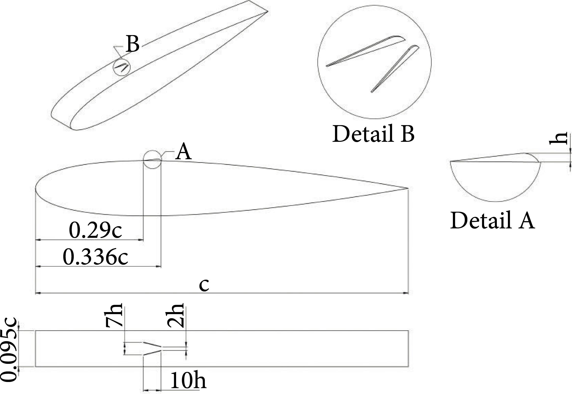
. The height of the VG was dimensioned in the same order of magnitude of the thickness of the boundary layer δ0.33c, AoA=3 = 1.1mm at the point where the generator (0.33c) is located.
The geometry is shown in Fig. 1, with the generator surface starting at 0.29c increasing linearly until it reaches VG height (h) = 1.2 mm at 0.33c and decreasing as an arc of circumference, until the distance of 0.336c.
NUMERICAL METHOD
The Navier-Stokes equations are solved using the finite element method with Altair HyperWorks CFD trading code, using the turbulence model of a Spalart-Allmaras (SA) equation.
The SA model was chosen because it presents sufficient accuracy to quickly solve the external boundary layer with adverse pressure gradient (Versteeg and Malalasekera 2007Versteeg HK, Malalasekera W (2007) An introduction to computational fluid dynamics: the finite volume method. 2nd ed. Edinburgh: Pearson Education.), more details about the model can be seen in the work of Spalart and Allmaras (1992)Spalart PR, Allmaras SR (1992) A one-equation turbulence model for aerodynamic flows. In: 30th Aerospace Sciences Meeting and Exhibit. Reno: AIAA . https://doi.org/10.2514/6.1992-439
https://doi.org/10.2514/6.1992-439...
.
The computational domain is represented in Fig. 2, the simulation had the studies concentrated in Rec= 2.38 × 10⁵ in AoA = 3 and 6. Figure 2 also shows the boundary conditions used in the simulation, numbered as: Region 1 (symmetry condition), Region 2 (free flow condition, which determine the conditions of the inflow and outflow of the domain), and Region 3 (no-slip condition, on the face representing the surface of the wing).
The mesh (Fig. 3) used in the boundary layer region contains prismatic volume elements, while the remainder of the domain is composed of tetrahedral volume elements.
VALIDATION
The validation of the results was performed with the airfoil without the vortex generator. Firstly, the validation of the code was performed using the wind tunnel data obtained from the work of Sheldahl and Klimas (1981)Sheldahl RE, Klimas PC (1981) Aerodynamic characteristics of seven symmetrical airfoil sections through 180-degree angle of attack for use in aerodynamic analysis of vertical axis wind turbines. Albuquerque: OSTI.GOV; 1981. Report No.: SAND-80-2114. https://doi.org/10.2172/6548367
https://doi.org/10.2172/6548367...
, who performed numerous wind tunnel tests of various airfoil profiles, including NACA 0015 airfoil.
The validation was done with the experimental data in Rec= 3.6 × 10⁵ because it was the experiment found closest to the conditions studied in the present work, for the validation three meshes were created: Mesh 1 = 1.7 × 10⁶, Mesh 2 = 3.1 × 10⁶, Mesh 3 = 5 × 10⁶ elements, presenting good results, as shown in Fig. 4 and Fig. 5. The mesh convergence was performed for all the tests carried out, being chosen the mesh with 5 × 10⁶ elements, due to the good convergence of the results, and a moderate computational cost (Fig. 4).
Lift coefficient (CL) as a function of the angle of attack comparing numerical result with the experimental data in wind tunnel.
Drag coefficient (CD) as a function of the angle of attack comparing numerical result with the experimental data in wind tunnel.
RESULTS
In Rec= 2.38 × 10⁵ and AoA = 3, the emergence of the expected separation bubble was observed, whose detachment of the boundary layer occurs at ∼ 0.34c and immediately reattach at ∼ 0.63c. Figure 6 shows a bluish region (low speed) extending a considerable percentage of the chord, which indicates that the fluid is being braked. According to the enlarged detail presented, it is evident that this is a region of recirculation with velocity vectors opposite to the flow.
When increasing the angle of attack for AoA = 6, the recirculation bubble travelling towards the leading edge can be observed, with the boundary layer detachment at ∼ 0.13c and reattaching at ∼ 0.33c. Figure 7 shows the field as well as the recirculation region.
EFFECT ON THE SPEED PROFILE AND DETACHMENT REGIONS
The study of the influence of the VG on Rec= 2.38 × 10⁵ was carried out based on three plans of measurement (Plan 1, Plan 2 and Plan 3), represented in Fig. 8, where wing width (S) = 24 mm.
The occurrence of well-defined counter-rotational longitudinal vortices extending over almost all extrados of the wing was observed in AoA = 3, a strong interaction of these vortices over the recirculation region was observed in the longitudinal region contained near to Plan 3 (Fig. 9).
Representation of detachment and reattachment regions over the wing without (left) and with (right) VG in Rec = 2.38 × 10⁵ and AoA = 3.
Figure 9 shows a comparative between the simulation without (left) and with (right) VG, where the red and blue lines are given by the program, representing the considered points of detachment and recollection by the software, respectively. Some random lines that appear do not physically represent the actual regions of detachment and recollection are generated due to some implied numerical error loaded in the model of analysis that estimates these regions. For clearer and representative results, the simulation with VG the regions that were actually considered the region of separation are delimited by a yellow line, this line was stipulated through a careful analysis of the flow based on the velocity vectors. This yellow line makes the interaction of vortices visible by adding kinetic energy and forming a sort of boundary layer aisle attached to the surface, where it was once a single large recirculation bubble.
The numerical analysis showed that the region below the longitudinal vortices location did not show detachment due to the greater amount of kinetic energy injected in the region near the surface in that region. While on the Plan 3 where the vortices meet, there is a strong interaction between them just after the VG inducing the increase of the velocity component in the normal direction of the surface, because the vortices are counter-rotating. This eventually generates a small region of boundary layer detachment and this reattachment increase in the turbulent flow intensity, which added the action of the vortices by throwing the fluid with low kinetic energy out of the boundary layer, making the boundary layer to remain attached to the surface along the rest way (Fig. 10).
The recirculation bubble would decrease considerably near the vortices, as can be seen from Fig. 10 and 14, which show the flow velocity profile along the wing (in comparison with profile without VG, Fig. 11). The vortices are seen more clearly through Fig. 15.
Velocity profile on NACA 0015 airfoil without VG in Plane 3 in Rec = 2.38 × 10⁵ and AoA = 3.
Velocity profile on NACA 0015 airfoil without VG in Plane 3 in Rec = 2.38 × 10⁵ and AoA = 6.
Perspective view of the transverse velocity profiles on the NACA 0015 airfoil with VG in Rec = 2.38 × 10⁵ and AoA = 3.
Perspective view of the longitudinal vortices generated by the VG in Rec = 2.38 × 10⁵ and AoA = 3.
The simulation in AoA = 6 showed that the recirculation bubble directly falls on the VG, which hinders the generation of vortices since the flow loses energy due to recirculation, this becomes more evident analyzing Figs. 12 and 16 (in comparison with profile without VG in Fig. 13), in which the velocity profiles are presented, in these conditions the emergence of well-defined vortex structures was not observed.
Perspective view of the transverse velocity profiles on the NACA 0015 airfoil with VG in Rec = 2.38 × 10⁵ and AoA = 6.
EFFECT ON THE PRESSURE DISTRIBUTION
The performance of the VG can also be observed in Fig. 17, where the pressure distribution is taken in Plans 1, 2 and 3 being compared to NACA 0015 airfoil.
Pressure distribution along Plans 1, 2 and 3 for NACA 0015 airfoil with and without VG in Rec = 2.38 × 10⁵ and AoA = 3.
Without a generator, the generator performance is evident mainly in Plane 3 (between the two surfaces of the VG). When analyzing the region downstream of the VG (after 0.29c), a pressure oscillation is observed first and a step format is identified in 0.38c; this step format indicates a sudden increase in pressure characteristic of reattached region. The reattachment point is followed by a considerable pressure increase between 0.4 and 0.58c, which is due to the fact that the vortices act on the boundary layer by removing the bubble from surface, being this recirculation region characterized by the loss of pressure (low pressure), and when removed, causes the local increase of Cp.
For AoA = 6, it was expected that the VG performance would be lower due to the emergence of the recirculation region before the generator. The pressure as expected was not much affected by the VG. Figure 18 shows that the pressure profiles with and without generator are coincident along almost any length of chord, except for the region near the VG where a slight increase of the pressure between 0.29c to 0.34c (region that contains the VG) can be observed.
Pressure distribution along Plans 1, 2 and 3 for NACA 0015 airfoil with and without VG in Rec = 2.38 × 10⁵ and AoA = 6.
EFFECT ON AERODYNAMICS
The main focus in the study of aerodynamics is mainly the search for ways to increase lift (L) and decrease drag (D). Usually work with L/D ratio to evaluate aerodynamic performance. Table 1 shows that the behavior of the results is in accordance with the expected results. It is possible to analyze that at AoA = 3 there was a subtle decrease in the lift of 0.83% due to the increase of the pressure generated by the VG, where in the previous time there was a low-pressure region due to recirculation on the extrados. Another observed point analyzes that at AoA = 3 there was a subtle decrease in the lift of 0.83% due to the increase of the pressure generated by the VG, where in the previous time there was a low-pressure region due to recirculation on the extrados. In this case the reduction of drag is due to the action of the longitudinal vortices removing the recirculation bubble in a limited region, resulting in an L/D gain of only 0.61%, but representing improvement of the drag, due to the removal of the detachment zone, a longitudinal portion lying near Plan 3.
Considering the surface of the VG result in the increased of friction drag, due to the increase of the surface wet area, it is possible to observe that the reduction of the recirculation bubble was enough to compensate this drag fraction added, leading to a net drag reduction of 1.43%.
When the wing was observed in AoA = 6, it was noticed that the effect of the generator was very small, due to the region of detachment being located before the VG. In those conditions, the increase of the wet area and the loss of linear moment of the fluid when finding with the fins cause the drag increase to be 0.33%; however, the small increase of 0.35% in the lift due to the new pressure distribution ends up compensating drag, generating the same value of L/D in practice.
ANALYSIS FOR NEW GEOMETRIES
This stage carried out a study character for comparison of the variation of detachment of surfaces and inversion of sense of VG are affect in lift and total drag to a condition of Rec= 2.38 × 10⁵ and AoA = 3, where a bubble of recirculation is present and after VG. The study was performed keeping fixed the height of the VG that worked so far, that is, h = 1.2 mm. In addition, the format and the location of the new VG geometry beginning at 0.29c and ending at 0.33c were also maintained.
The simulations were separated into three groups represented in Fig. 19, which was classified in the sequence.
The basic geometry of the VG that has been studied so far and is described in Fig. 1 was named as VG01 whose value of the β = 14.01º, N = 2, and consequently, D1 = 2 h and D2 = 7 h. It would serve as a base geometry to evaluate the effect of variation of and N.
The parameter N in group A defines proportionally the variation of the smaller (D1) and the greater distance (D2) between the surfaces of the VG, maintaining β = 14º, where N is correlated by D1 = Nh and D2 =(N+5)h. For group B, the value of β was changed, keeping a fixed value of D1 = 2 h. For group C the inverted geometry of VG01 (rotated 180º) was considered. The geometric parameters as well as the nomenclature of the developed geometries are detailed in Table 2.
Table 3 presents the results of the simulation analyzed in group A, where the increase of the drag is observed, as the surfaces move away as N increases, and the geometry of VGA1 is the one that best presents performance with less drag and lift among the other generators. The simulations of Group A indicated that the approximation of surfaces results in improved aerodynamic performance, less drag and more lift, being the best results obtained in N = 0 (VGA1) with the improvement of L/D in 2.56% while the VGA3 did not bring any benefit compared to wing without VG. Group B analysis indicates that the increase in β clearly worsens drag and lift, being VG01 with β = 14º the only geometry that showed better performance in relation to the wing without VG. Group C, in which the geometry VG01 was rotated 180º, resulted in a change in the direction of rotation of the vortices; the results show an evident loss of lift and increase of drag.
CONCLUSIONS
This paper addressed the influence of a vortex generator on a wing with NACA 0015 airfoil at low angles of attack. The study was divided into two cases.
The first case characterized by the occurrence of a separation bubble shortly after the VG showed that the VG performance resulted in a significant decrease of the separation bubble, mainly in the areas near the Plan 3, leading to a small pressure gain that resulted in drag reduction by 1.43%, as well L/D gain of 0.61%.
The second case was interesting to analyze the ability of VG to form vortices when the bubble separates over it, under these conditions no well-defined vortex structures were observed, due to the fact that the recirculation zone decrease part of the linear momentum that would be used to generate the longitudinal vortices. However, even in the face of this fact, a small change in the pressure distribution close to the VG was observed compared to the database, which results in an increase of 0.35%, in contrast to the drag which also increases around 0.33%, almost without influencing the ratio L/D.
The VG is an alternative for the NACA 0015 airfoil at low angle of attack and Rec to lower the detachment region when it is located before detachment. However, for the conditions where this region happens to affect the generator, the use of VG is not strongly justified, but its presence has little influence on the final aerodynamic performance of the wing, since the increase in drag is compensated by the increase in lift.
The results presented showed that the VG is inefficient in generating the vortex structures when it is located inside a recirculation zone, in contrast when situated prior to this recirculation bubble, where it is able to considerably reduce the region of detachment.
An analysis was also carried out to evaluate how the changes in some geometric parameters affected wing performance, and the following conclusions were made: drag and wing lift are improved by decreasing distance D1 and D2 (as a function of N) while maintaining β = 14º, for β > 14º drag and lift are harmed, in addition, the rotation by 180º (inversion) of the geometry of the VG worsened drag and lift.
ACKNOWLEDGMENTS
The authors would like to thank Rafael Gigena Cuenca for his comments regarding the research, and the Scientific Computing Laboratory at Federal University of Santa Catarina. Editors and authors are thankful to Fundação Conrado Wessel for providing the financial support for publishing this article.
REFERENCES
- Ashill PR, Fulker JL, Hackett KC (2001) Research at DERA on sub boundary layer vortex generators (SBVGs). In: 39th Aerospace Sciences Meeting and Exhibit. Reno: AIAA. https://doi.org/10.2514/6.2001-887
» https://doi.org/10.2514/6.2001-887 - Ashill PR, Fulker JL, Hackett KC (2005) A review of recent developments in flow control. Aeronaut J. 109(1095):205-232. https://doi.org/10.1017/S0001924000005200
» https://doi.org/10.1017/S0001924000005200 - Booker CD, Zhang X, Chernyshenko SI (2011) Large-scale vortex generation modeling. J Fluids Eng. 133(12):121201. https://doi.org/10.1115/1.4005314
» https://doi.org/10.1115/1.4005314 - Fouatih OM, Madale M, Imine O, Imine B (2016) Design optimization of the aerodynamic passive flow control on NACA 4415 airfoil using vortex generators. Eur J Mech B Fluids. 56:82-96. https://doi.org/10.1016/j.euromechflu.2015.11.006
» https://doi.org/10.1016/j.euromechflu.2015.11.006 - Gao L, Zhang H, Liu Y, Han S (2015) Effects of vortex generators on a blunt trailing-edge airfoil for wind turbines. Renew Energy. 76:303-311. https://doi.org/10.1016/j.renene.2014.11.043
» https://doi.org/10.1016/j.renene.2014.11.043 - Gardarin B, Jacquin L, Geffroy P (2008) Flow separation control with vortex generator. In: 4th Flow Control Conference. Seattle: AIAA. https://doi.org/10.2514/6.2008-3773
» https://doi.org/10.2514/6.2008-3773 - Katz J, Morey F (2008) Aerodynamics of large-scale vortex generator in ground effect. J Fluids Eng. 130(7):071101. https://doi.org/10.1115/1.2948361
» https://doi.org/10.1115/1.2948361 - Kerho M, Hutcgerson S, Blacwelder RF, Liebeck RH (1993) Vortex generators used to control laminar separation bubbles. J Aircr. 30(3):315-319. https://doi.org/10.2514/3.46336
» https://doi.org/10.2514/3.46336 - Kuya Y, Takeda K, Zhang X (2010) Computational investigation of a race car wing with vortex generators in ground effect. J Fluids Eng. 132(2):021102. https://doi.org/10.1115/1.4000741
» https://doi.org/10.1115/1.4000741 - Kuya Y, Takeda K, Zhang X, Beeton S, Pandaleon T (2009) Flow physics of a race car wing with vortex generators in ground effect. J Fluids Eng. 131(12):121103. https://doi.org/10.1115/1.4000423
» https://doi.org/10.1115/1.4000423 - Lin J (1999) Control of turbulent boundary-layer separation using micro-vortex generators. In: 30th Fluid Dynamics Conference. Norfolk: AIAA. https://doi.org/10.2514/6.1999-3404
» https://doi.org/10.2514/6.1999-3404 - Lin J, Howard F, Selby G (1991) Exploratory study of vortex-generating devices for turbulent flow separation control. In: 29th Aerospace Sciences Meeting. Reno: AIAA. https://doi.org/10.2514/6.1991-42
» https://doi.org/10.2514/6.1991-42 - Manolesos M, Voutsinas SG (2015) Experimental investigation of the flow past passive vortex generators on an airfoil experiencing three-dimensional separation. J Wind Eng Ind Aero. 142:130-148. https://doi.org/10.1016/j.jweia.2015.03.020
» https://doi.org/10.1016/j.jweia.2015.03.020 - Robarge T, Stark A, Mim S-K, Khalatov A, Byerley AR (2004) Design considerations for using indented surface treatments to control boundary layer separation. In: 42nd AIAA Aerospace Sciences Meeting and Exhibit. Reno: AIAA. https://doi.org/10.2514/6.2004-425
» https://doi.org/10.2514/6.2004-425 - Schilichting H (1979) Boundary-layer theory. New York: McGraw-Hill.
- Sheldahl RE, Klimas PC (1981) Aerodynamic characteristics of seven symmetrical airfoil sections through 180-degree angle of attack for use in aerodynamic analysis of vertical axis wind turbines. Albuquerque: OSTI.GOV; 1981. Report No.: SAND-80-2114. https://doi.org/10.2172/6548367
» https://doi.org/10.2172/6548367 - Spalart PR, Allmaras SR (1992) A one-equation turbulence model for aerodynamic flows. In: 30th Aerospace Sciences Meeting and Exhibit. Reno: AIAA . https://doi.org/10.2514/6.1992-439
» https://doi.org/10.2514/6.1992-439 - Tebbiche H, Boutoudj MS (2014) Optimized vortex generators in the flow separation control around a NACA 0015 profile. In: Proceedings of the 9th International Conference on Structural Dynamics. Porto: Eurodyn.
- Troldborg N, Sørensen NN, Zahle F, Réthoré P-E (2015) Simulation of a MW rotor equipped with vortex generators using CFD and an actuator shape model. In: 53rd AIAA Aerospace Sciences Meeting. Kissimmee: AIAA. https://doi.org/10.2514/6.2015-1035
- Versteeg HK, Malalasekera W (2007) An introduction to computational fluid dynamics: the finite volume method. 2nd ed. Edinburgh: Pearson Education.
- Veryan SA, inventor. Solid boundary surface for contact with a relatively moving fluid medium. United States patent US 2800291A. 1950.
- Wheeler GO, inventor; Cessna Aircraft Co. Means of maintaining attached flow of a flow medium. United States patent US 4455045A. 1981.
- Wijdeven TV, Katz J (2013) Simulation of a MW rotor equipped with vortex generators using CFD and an actuator shape model. 53rd AIAA Aerospace Sciences Meeting.
- Zhang L, Li X, Yang K, Xue D (2016) Effects of vortex generators on aerodynamic performance of thick wind turbine airfoils. J Wind Eng Ind Aero. 156:84-92. https://doi.org/10.1016/j.jweia.2016.07.013
» https://doi.org/10.1016/j.jweia.2016.07.013
Edited by
Publication Dates
-
Publication in this collection
15 May 2020 -
Date of issue
2020
History
-
Received
06 Feb 2019 -
Accepted
26 June 2019