ABSTRACT
Since atmospheric winds play the most critical natural enviroment (NE) role as input into the design and development of an aerospace launch vehicle, this paper provides a more detailed description of the wind environment and its interaction with engineering design in launch and space vehicle development applications at Kennedy Space Center (KSC).
KEYWORDS:
Terrestrial Environment; Wind Characteristics; Ground Winds; Winds Aloft; Vehicle Design
INTRODUCTION
This is the third historical paper which concludes what the previous two papers (Johnson and Vaughan, 2019Johnson DL; Vaughan WW (2019) The Role of Terrestrial and Space Environments in Launch Vehicle Development. J Aerosp Technol Manag, 11: e4719. https://doi.org/10.5028/jatm.v11.1088
https://doi.org/10.5028/jatm.v11.1088...
and Johnson and Vaughan, 2020Johnson DL; Vaughan WW (2020) Key Terrestrial And Space Environment Sources. J Aerosp Technol Manag, 12: e0120. https://doi.org/10.5028/jatm.v12.1089
https://doi.org/10.5028/jatm.v12.1089...
) presented, dealing with the subject of the role of the Earth’s terrestrial and space natural environment involvement in launch vehicle design and development.
The response of a launch vehicle to wind disturbances is very complicated because the vehicle’s response depends on and interacts with the characteristics of the wind-magnitude, shear, gust, etc., the vehicle dynamics (rigid body, elastic body, propellant oscillations, etc.), and the control system.
The determination of a launch vehicle’s response to atmospheric disturbances cannot be reduced to the analysis of one discrete set of response criteria, such as vehicle loads, but must include many response parameters dependent upon the vehicle configuration and specific mission. It is not practical to use only one type of NE design criteria input for all phases of vehicle design. Different approaches and methods of evaluation must be used as the particular phase demands. The phases include preliminary design, final structural design, guidance and control (G&C) system design and optimization - preliminary and final, and establishment of limits (constraints) and procedures for launch and flight operations.
Vehicle design phases interact, as well as launch and flight operations. In each phase, the following must be considered. The choice of the methods for NE analysis and the choice of an analytical dynamic model to describe the vehicle characteristics relevant to a particular design phase must be determined. For example, a rigid body analysis may be adequate for preliminary structural design, and full elastic simulation (generating loads envelopes) could be used for the final design. Likewise, the Vector Wind Profile (VWP) model or a discrete synthetic wind profile may be adequate for preliminary design, while final design and flight operations capability may require individual detailed Jimsphere measured winds. Johnson (2008)Johnson DL (2008) Terrestrial environment (climatic) criteria guidelines for use in aerospace vehicle development, 2008 Revision. (TM-2008-215633). NASA Technical Memorandum. provides an extensive overview of the different NE design criteria guidelines for use in aerospace vehicle development.
The main perturbing forces for launch vehicles, both on the launch pad and in flight, are the aerodynamic loads produced by winds. Because the wind loads are a major structural consideration, they greatly influence the design of the vehicle’s flight control system. Since wind is the most important atmospheric parameter influencing the design of a launch vehicle, wind as input has been selected here as an example to illustrate the importance of the terrestrial environment considerations in the launch vehicle design and development process.
GROUND WINDS
Ground or surface winds are generally defined here as < 150 m. In-flight (or aloft) winds are from 150 to ~80 km altitude. A launch vehicle exposed to surface winds for more than a few hours while erected on the launch pad may be subjected to critical wind loads, elevating the risk for vehicle damage as exposure time increases. Since wind is a vector quantity that varies both in space and time, the wind loads should be considered as a dynamic input to the vehicle structure. From an aerodynamic point of view, the problem falls in the category of viscous separated flow around a bluff body. Although such flows have been studied for years, an adequate approximation to aerodynamic transfer functions to relate the dynamic wind vector to the dynamic load on the body does not exist. Therefore, quasi-steady assumptions must be used. To further simplify the problem, the near-surface wind profile is broken down into steady-state (mean) and unsteady components (Fig. 1), with resulting static and dynamic loads superposed (Geissler 1970Geissler ED (1970) Wind effects on launch vehicles. Slough: Technivision Services.). The second-order loads resulting from the interaction of the static and dynamic wind components can be neglected in the present state of the art.
Launch vehicle exposed to steady state (mean) and unsteady component for ground winds (Geissler, 1970).
Low-Level Wind Profile. Since the Earth’s surface exerts a frictional force on the lower layers of the atmosphere, this causes a decrease in the average wind speeds near the surface. Assuming that stress is proportional to the vertical wind shear, and that the proportionality constant varies linearly with height, the steady-state wind speed profile may be represented by a logarithmic function of height. This representation turns out to be approximately valid during neutral to slightly unstable stability conditions, which usually include high wind speeds. An empirical representation of this function (Eq. 1) that has been widely used in scientific and engineering work, is called the power law:
where U = wind speed at height h; U1 = wind speed at a reference height h1; exponent p = function of wind speed, ground roughness, stability, etc., and increases as the wind speed decreases.
Once p is known, the wind speed needs only to be measured at the reference height to define the entire profile envelope to a height of ~150 m. For purposes of establishing design envelopes, especially for the moderate ground roughness conditions that exist for KSC, a value for p of 0.20 is usually employed when the 3-m height, steady-state wind speed is between 7 and 15 m/s. A KSC p value of 0.14 has been used when the steady-state wind speed is between 22 and 30 m/s. Therefore, using the power law profile, wind measurements at any height may be translated to any other height. See Johnson (2008)Johnson DL (2008) Terrestrial environment (climatic) criteria guidelines for use in aerospace vehicle development, 2008 Revision. (TM-2008-215633). NASA Technical Memorandum. and Smith and Adelfang (1998)Smith OE, Adelfang SI (1998) A compendium of wind statistics and models for the NASA space shuttle and other aerospace vehicle programs. (CR-1998-208859). NASA Technical Report. for application.
Wind Shear. Structural loading exists on the vehicle while it is anchored on the launch pad. A symmetric vehicle behaves as a cantilevered beam with wind pressures producing bending moments that increase continuously from zero at the vehicle’s nose to a maximum at the base as do the vehicle’s axial dead weight loads.
Wind shear near the surface, for design purposes, is a shear that acts on a launch vehicle free standing on the pad or at the time of lift-off. This design wind shear was initially computed from the selected design percentile wind speed envelope by using the peak wind speed at the top of the vehicle and the quasi-steady-state wind speed at the base of the vehicle with respect to height of the base above the true ground. In some cases, the base of the vehicle will be elevated above the ground, which must be taken into account.
Gust. For design purposes, the discrete gust shape for the higher surface wind conditions and in-flight wind conditions is represented by a wedge shape, with linear increase to the peak wind in 2 s and then linear decay to the steady-state value in 1 s. The gust factor is known to be a function of the steady-state wind speed, time average of the wind speed, stability conditions, terrain features, and height. A gust factor of 1.4 has been used at KSC to obtain the design peak wind speed.
Turbulence Spectra. The spectra of the lateral, longitudinal, and vertical wind velocity components are, in general, different, and a function of stability and local terrain features. For most engineering applications, it appears desirable to compute the spectra of turbulence for the specific location of interest. See Power Spectral section for a more thorough description.
Wind Loads Rules of Thumb. A customary practice during the preliminary design phase of a vehicle is to estimate the steady drag bending moment corresponding to the expected peak wind, allowing a 50% margin for dynamic loads. This estimate can be un-conservative for some vehicle configurations. The static and dynamic loads are then finalized by testing an aeroelastic model in the wind tunnel after the structural design of the vehicle is nearly finalized. Wind azimuth is also a primary input variable, especially for a nonsymmetrical vehicle like the Space Shuttle.
Unsteady drag and lift resulting from a steady wind can be attributed to three sources: (1) Vortex shedding, (2) buffeting, and (3) galloping excitation. Power spectral concepts have been used to describe the fluctuating wake velocities and pressures and the forces on a bluff body.
Static and dynamic loads due to winds can be combined vectorially to obtain the final load, and is believed to provide a conservative estimate. Since most of these loads can be determined to some extent in the design phase, the structural integrity of the vehicle will be, in general, jeopardized only by unexpectedly large vortex shedding loads. In this case, a study should be made of launch pad operations to determine the timeframe of vehicle exposure and the associated risk of structural damage, or launch delay. Extended exposure to the wind field of the unprotected vehicle should be avoided and the risk associated with any proposed on-pad stay time schedule should be established. This risk includes not only structural damage but also the possibility of schedule slip or failure to obtain a desired launch date or time. This entire ground wind loads problem and solution is discussed in chapter 3 of Geissler (1970)Geissler ED (1970) Wind effects on launch vehicles. Slough: Technivision Services..
A damper connecting the vehicle to the umbilical tower generally reduces the vortex shedding loads along with the dynamic loads caused by atmospheric turbulence, but does not reduce the effect from steady-state winds. Therefore, the risk of wind damage to the vehicle can be significantly decreased for a reasonable on-pad exposure time, e.g., to < 1% for Saturn-type symmetrical vehicle configuration, for a pad stay time of 30 days.
Vortex Shedding/Stop Sign Flutter for Symmetric and Nonsymmetric Launch Vehicles. A symmetrical launch vehicle has been analyzed for classical vortex shedding using both analytical and scale model testing. Being essentially a cylinder, the vehicle showed clear vortex shedding problems, particularly since it must spend up to 30 days on the pad exposed to ground winds. As a result, wind velocity criterion was then used which required installation of a damper when above critical wind levels were being predicted, or during any free-standing time on the pad. Bending moment capability is a function of maximum ground wind speed. Pearson et al. (1996)Pearson SD, Vaughan WW, Batts CW, Jasper GL (1996) Importance of the natural terrestrial environment with regard to advanced launch vehicle design and development. (TM-108511). NASA Technical Memorandum. present these bending effects versus wind speed.
A nonsymmetrical launch vehicle configuration may not be susceptible to classical vortex shedding, but falls into the arena of the classical stop sign flutter (named from road signs fluttering at certain critical frequency wind speeds). Scale model wind tunnel tests are usually needed to verify the stop sign flutter potential. The flutter limit may be determined relative to the pad vehicle interface stiffness. Final design may show no stop sign flutter problem due to the naturally large torsional stiffness arising from the vehicle configuration and the hold-down/supports.
Lift-Off Aerodynamics: Vehicle Drift/Twang Loading. Wind has a significant effect on the launch vehicle during the period from just before release of the hold-down mechanism until the vehicle has completely cleared the launch tower structure. The major wind problem during launch is that of vehicle drift just after release and during initial ascent. It is assumed for these analyses that the vehicle at lift-off is in an undeflected state such that its initial motion is vertical. Under these conditions, bending moments induced on the vehicle are smaller than those experienced at later flight times, or in the hold-down position before launch, when ground winds may surpass the allowable values for launching. Very large forces and moments can be induced in the vehicle if it collides with the tower or vehicle hold-down mechanism. Nonuniform wind velocity profiles exist over the vehicle length before and at lift-off. After clearing the towers, a more uniform cross-flow velocity and angle-of-attack distribution exist.
A related phenomenon at lift-off that needs to be considered, commonly called twang loading, is an effect (force) on the vehicle caused when the vehicle base is released to the free mode. A wind-loaded, bent vehicle will tend to snap straight at the instant of release. Although longitudinal shock loading on the vehicle from the release of the hold-down mechanism is important, it is essentially independent of wind conditions.
IN-FLIGHT WINDS
As stated earlier, in-flight (or aloft) winds are normally defined as occurring and being applied from 150 m to ~80 km altitude. Winds and wind load effects on an airframe structure, on vehicle G&C, etc. are needed for launch vehicle flight capability design and operability. Mission analysis simulations, wind models, wind profiles, and power spectral analyses can be used to simulate wind flow, wind shear, gust, and turbulent effects on a vehicle in flight, while wind monitoring and load relief systems can help alleviate various wind-associated engineering problems in flight. These areas are discussed within this subsection.
Structural/Airframe Design. Wind-induced forces and bending moments are the basis for the design of the vehicle (structure), since there is a large impact of the wind effects upon vehicle configuration design. Rigid body flight loading accounts for the gross overall motions of the vehicle as it responds to wind forces during flight. The vehicle can rotate, translate, and depending on the G&C scheme philosophies, may allow it to drift, to turn into the wind, or maintain the original trajectory. Since the choice of control philosophy is so important in determining the loads on the vehicle, rigid body analyses should be performed early in preliminary design before vehicle flexibility is introduced. However, structural loading due to ground winds before and during lift-off is also important. Analyses of elastic body motions of the vehicle, and that of propellant sloshing, are important in the final configuration, especially for propellant tank locations and airframe.
Wind Load Effects on Structure. Upper-level winds in the high dynamic pressure (max-q) region, typically between 10 and 15 km altitude, is the most significant terrestrial environment element affecting structural design. In-flight elastic body deformations whose magnitudes and resultant bending moments are strongly dependent on the relative frequencies of wind gusts and turbulence, as well as on the modes of body bending, propellant slosh, control, and engine. Vehicle system stability depends on the spacing of these influences and modal frequencies.
The total elastic response of the vehicle to in-flight winds is generally considered in terms of the three main bending moments. Moments due to angle of attack are direct wind load moments. The others are those due to engine-deflected thrust (as the control system gimbals the engines in response to the rigid body motions of the vehicle), and those due to those induced by the dynamic elastic response of the vehicle airframe and the sloshing of propellants. The response of the vehicle to distributed and randomly varying wind forces, as well as engine forces, is much more complex in terms of vehicle response characteristics.
During flight, the maximum bending moment and lateral shear load resulting from wind effects occur shortly after launch. The maximum bending moment, combined with the associated axial compression loads, constitutes the critical design condition (critical loading at max q α). Beyond this altitude, the wind effects diminish.
Guidance and Control Systems. The G&C systems of a launch vehicle act together to cause the vehicle to fly a desired flight path, with each system having its own particular requirements. The guidance system determines the flight path to achieve desired end conditions, whereas the control system is to enforce the correct attitude of the vehicle in order to achieve the desired flight path. The guidance system must also correct for anomalies in the vehicle and in its environment, such as variations in air density and disturbances such as winds. The control system is to provide correction for anomalies and disturbances that affect the control system operation. Anomalies include variations in predicted structural bending characteristics, while the major disturbances are thrust misalignments and wind, with wind being by far the more significant of the two.
Wind Effects on Guidance System. The ascent wind profile effects come into play when the guidance system attempts to meet the objective of maximizing payload. There are two ways to accomplish this. One is the flight-mechanical effect of optimizing the lift-drag-direction relationship for a trajectory through the Earth’s atmosphere and gravitational field. The second factor on which the wind has a direct influence is the effect of flight path on vehicle bending moment, and hence on structural weight. Bending moment is caused by control forces, i.e., engine gimbaling, and by aerodynamic side forces induced by side winds and vehicle maneuvering. Therefore, in choosing the optimal flight path, the guidance system must consider not only the flight mechanical aspects, but also the wind-induced bending moments.
While the vehicle is within the sensible atmosphere, the bending moment considerations are much more significant than the other flight mechanical effects. Vehicle guidance can be accomplished by a zero-lift tilt program, which commands the control system in attaining a zero-lift trajectory.
Since there is a large variation in probable wind magnitude and azimuth from month to month, it has been common practice to assume that the expected wind is zero (zero mean for launches throughout the year) in order to minimize the bending moment. This assumes that the tilt program assumes no wind disturbances and the guidance system output commands a trajectory that will produce zero side force if the nominal wind is actually encountered. If the actual wind encountered is equal to the nominal wind, and if the control force exerted is negligible, the zero-lift trajectory is the minimum bending moment trajectory. But if the launch is narrowed to one or two months, then the mean wind may be nonzero. Then it may be advisable to incorporate the mean wind information as a bias in the tilt program.
The biased tilt program will then ensure that a zero-lift trajectory is flown if the nominal wind is encountered. This procedure is called wind biasing. Many vehicle guidance systems today have gotten away from using monthly mean wind profiles as input, but currently use the real-time measured wind profile as input into their tilt programs. This allows for a wind bias of a much shorter time period than a month, thereby reducing the region of uncertainty about the nominal wind, and reducing the possible bending moment values for the vehicle. This would hold true if wind persistence prevailed throughout the countdown. The winds also have an influence through its effect on the terminal trajectory dispersion of first-stage flight for a multi-staged vehicle. Today, many launch vehicle guidance systems use a real-time, measured wind profile within its guidance algorithms for its commands. An example is the DOLILU (day of launch ILOAD update) used for the Space Shuttle.
Wind Effects on Control System. Upper-level winds in the high dynamic pressure (max-q) region, typically between 10 and 15 km altitude, is the most significant terrestrial environment element affecting control system design. Since the control system functions primarily to maintain a prescribed flight path as generated by guidance on preprogrammed attitude tilt commands, both off-nominal values of vehicle parameters and the presence of winds will cause the flight path to differ from that anticipated by the guidance system. Ideally, the control system should minimize this difference. However, there is a cost incurred in attempting to respond precisely to the guidance commands. The cost appears in terms of bending moments and resulting structural loading on the vehicle plus drift, and later thermal loads when the vehicle corrects for flight path deviations. The fact that winds are acting on the vehicle could make this cost excessive.
Winds aloft are frequently of such a large magnitude, especially in the max-q region, that large dispersions in guidance system-prescribed attitude and flight path angles occur. In order for the control system to decrease these dispersions, large bending moments are imposed on the vehicle. If a controller is being designed for an already designed vehicle structure, these loads can be so large that the vehicle would exceed its design loads and break up.
On the other hand, if the control system design is for a vehicle in the preliminary design stage so that structural requirements are yet to be established, the large bending loads can result in excessively complex, heavy, or expensive structural configurations. Consequently, because of the in-flight winds, bending moments on the vehicle become the overriding consideration in controller design. Structural bending (involving winds) affects the control system’s roles in two ways - through both forward loop and feedback loop coupling.
-
Control Frequency. A factor affecting the control frequency is vehicle bending moment. High frequencies cause the control system to react fast to wind disturbances, resulting in large gimbal angles. Also, low frequencies produce a more sluggish gimbal response, thereby permitting larger values of angle of attack when a wind is encountered. The best frequency depends on the relative contributions of aerodynamic and thrust forces to vehicle bending moment. Thus, whether aerodynamic or thrust forces dominate, the bending moment depends upon an additional factor, the characteristic of the wind disturbance. Winds with high shear and gust content usually cause large transients in the control loop, and consequently large gimbal angles. On the other hand, winds low in shear and gust content cause a slow buildup in angle of attack and usually bring small gimbal angle requirements.
-
Wind Models Used for Control Studies. Since winds are a dominant factor in system design, what wind models should be used in designing an acceptable control system? Several wind models are available and the particular one chosen depends on several factors, including the particular design philosophy. Should the system be designed for a low probability of failure due to winds, or a greater risk of failure be accepted? A second but important factor is the particular phase of the launch vehicle design problem under consideration. The first phase usually uses simplified mathematical models of the physical system being studied, while subsequent phases use models with increasing detail and accuracy. With the reference attitude being vertically upward in yaw-plane motion, the wind (U) is assumed to act transverse to the pitch plane. Initially, the way of representing the wind for use in control system design studies has been by using the synthetic wind profile (wind speed and wind shear values) as a function of altitude for different probability levels. Currently, the VWP model is frequently employed (Smith and Adelfang 1998Smith OE, Adelfang SI (1998) A compendium of wind statistics and models for the NASA space shuttle and other aerospace vehicle programs. (CR-1998-208859). NASA Technical Report.; Adelfang et al. 1994Adelfang SI, Smith OE, Batts GW (1994) Ascent wind model for launch vehicle design. J Spacecraft and Rockets 31(3):502-508. https://doi.org/10.2514/3.26467
https://doi.org/10.2514/3.26467... ; Smith 1976Smith OE (1976) Vector wind and vector wind shear models 0 to 27km altitude for Cape Kennedy, Florida and at Vandenberg AFB, California. (TM-X-73319). NASA Technical Report.; Adelfang 1999Adelfang SI (1999) User’s guide for monthly vector wind profile model. (CR-1999-209759). NASA Technical Report.). -
Wind gust/turbulence. Wind gust data used in control system design offers simplified rectangular-, triangular-, or sinusoidal-shaped gusts, since a good statistical representation of the fine structure of the wind is lacking. However, control design analysis also uses simplified representations for gusts, such as altitude duration, wavelength, versus amplitude of gust for different probability levels. For the Saturn example, in using vehicle trajectory data relating altitude to time, histories of the wind can be constructed from the wind profile and shear values given, resulting in a synthetic wind speed versus time profile.
-
Rule of thumb. A rectangular gust shape can then be superimposed at the time of peak wind speed, thereby producing a synthetic wind profile used in control design that combines the largest shear values with the highest gust at the point of peak wind speed. Since a design based on such a wind is very conservative, shear and gust values have been reduced by a percentage (15% in the Saturn case) based on engineering judgment since the largest shears and largest gusts are not likely to occur at the same time or altitude (Fig. 2). A less conservative approach can use a lower probability level wind speed and wind shear curves. Stochastic models of the wind have also been used in synthesizing control systems, and for analyzing the performance of an already designed system. Of course, as a less conservative design approach is employed, the risk for launch delay due to adverse wind effects in the maximum dynamic pressure (max-q) region increases. See section Description of Wind Shear, Gust, and Turbulence Models for further discussion on applications of turbulence and gusts to launch vehicles.
-
Wind Examples and Risk:
-
Shuttle. The solid rocket boosters (SRBs) on a nonsymmetrical Shuttle launch vehicle configuration initially had no control capability. As a result, the solid rocket motor nozzle flex bearing was redesigned and baselined. Two factors were used very early in the design and development period to take out conservatism, save weight and cost, and improve performance. They were as follows: (1) monthly mean wind biasing was instituted as part of criteria change for generating environments and performance, etc.; and (2) prior programs used the worst month reference period 95% wind speed in conjunction with the 99% wind shear and 99% gust as a conditional probability approach. The new launch vehicle configuration used 95% wind speed in combination with one-half the shear and gust 99% levels, then root sum squaring the other half with the other vehicle response parameters, again reducing margins. In addition, prelaunch monitoring of the ascent wind loads provided added assurance of a safe transition through the max-q region relative to wind loads. However, what these actions did was take out margins for flexibility, operations, and unknown vehicle effects.
-
Worst wind. For linear control systems, the worst month reference period wind used in deter- mining loads for structure design is the wind which causes the vehicle to experience maximum structural loading. For linear control systems, design experience has led to the selection of wind values such as 95% wind speed and 99% wind shear and gusts in constructing a synthetic wind profile that serves as the design worst month reference period wind. When nonlinear feedback systems are employed, such as load relief, winds must still satisfy the statistical stated constraints, but the wind profile constructed using extreme values will not necessarily be the worst wind. Techniques are needed to help determine what the worst disturbance will be for any particular control law. Today, this synthetic wind profile method has been supplemented in most analyses with the MSFC VWP model (Smith and Adelfang 1998Smith OE, Adelfang SI (1998) A compendium of wind statistics and models for the NASA space shuttle and other aerospace vehicle programs. (CR-1998-208859). NASA Technical Report.; Adelfang et al. 1994Adelfang SI, Smith OE, Batts GW (1994) Ascent wind model for launch vehicle design. J Spacecraft and Rockets 31(3):502-508. https://doi.org/10.2514/3.26467
https://doi.org/10.2514/3.26467... ; Smith 1976Smith OE (1976) Vector wind and vector wind shear models 0 to 27km altitude for Cape Kennedy, Florida and at Vandenberg AFB, California. (TM-X-73319). NASA Technical Report.; Adelfang 1999Adelfang SI (1999) User’s guide for monthly vector wind profile model. (CR-1999-209759). NASA Technical Report.). -
Stochastic methods. The use of a synthetic, deterministic wind profile as a design wind estimates a given probability level of wind disturbance, which may not precisely represent the desired percentile wind that results in applying a conservative and more robust design approach in defining uncertainties in wind effects. But if the wind could be treated as a statistical quantity, one can design to the desired probability level, if the vehicle model and wind model are both sufficiently restricted. The wind assumption is that the wind can be described as a Gaussian, time-varying random process with known characteristics. The two drawbacks in control system design are that the wind may not be Gaussian and the wind statistics need to consist of a sufficient quantity of accurately measured wind data.
-
Wind monitoring:
-
Day of launch. Launch vehicles are designed to accommodate a high percentage of occurrences of in-flight winds, minimizing the risk for launch delay. But there still is a finite possibility of winds occurring that will exceed the structural or control capability of the vehicle. Therefore, winds aloft can be closely monitored during the last 6 to 12 h before launch in order to minimize the risk involved at launch. Concerted efforts towards adequate design of airframe and control system should be made to reduce such risks. The limited launch windows for some launch vehicle missions illustrate this need.
-
Test and operational. Knowledge of the terrestrial environment is also necessary for establishing launch vehicle test requirements, and is used in the design of associated support equipment. Such data are required to define the fabrication, storage, transportation, test, and preflight design conditions and should be considered for both the whole system and the components which make up the system. For vehicle test and operations, areas of the terrestrial environment that need to be more carefully monitored prior to and during these events will benefit from the assessment of the terrestrial environment within the early design stages of the new launch vehicle development program.
-
Advanced Load Relief Systems. Advanced control methods for load relief can also reduce vehicle bending moment. Since bending moment depends on the form and magnitude of the wind disturbance, it is reasonable to consider advanced load relief systems that adapt to changes in disturbance force (input adaptive systems). Input adaptation to wind may be thought of as a general extension of the concept of wind biasing used for the guidance system. It attempts to compensate for the actual wind disturbances as they are encountered. The problems in designing such a system are sensing the wind value and determining what action to take in adjusting the control law for the measured wind value. Although the maximum bending moment within the class of winds considered can be reduced by the switched integral controller, there can still be an undesirable sensitivity to the wind magnitude. Wind shear reversal in the maximum dynamic region is an issue for adaptive control systems.
In the pre-Saturn and early Saturn days, for wind load alleviation, launch vehicles used adjustment of first-stage guidance in the pitch-plane relative to the monthly mean pitch-plane wind. During later Skylab and Apollo launches, adjustment of the guidance in both the pitch and yaw planes relative to the monthly mean pitch and yaw plane wind components were used to achieve additional wind loads relief. During Shuttle, further reductions were accomplished by selecting launch guidance from trajectory runs which produced the minimum loads using a day of launch (DOL) measured wind profile.
More recently, Shuttle first-stage guidance is derived based on analysis of a trajectory simulation using a measured Jimsphere wind profile obtained at T-4.5 h. This produces the smallest ascent loads dispersions achieved to date. It is called day-of-launch ILOAD update or DOLILU, where ILOAD represents ascent guidance. When DOLILU is used, it is the wind profile perturbations of approximately < 6,000-m wavelength that force control system responses to maintain the guidance path. Therefore, even the largest wavelengths in a wind profile could contribute to load indicator dispersions because these large wavelengths could deviate from the monthly mean component (vector) wind profile that was previously used to establish ascent guidance.
Wind-Vehicle Aerodynamic Loads Analysis. In principle, it is possible to compute the responses of a launch vehicle to a large number of high-resolution wind profiles and to evaluate the results in a Monte Carlo-type statistical analysis. However, this is both expensive and time consuming, especially if one wants to assess the influence of various system and control parameters on the vehicle responses. The statistical techniques of dynamic analysis attempt to avoid the disadvantage of the Monte Carlo approach by relating the statistics of the input (wind) to the statistics of the output (loads) of a dynamical system (launch vehicle). In preliminary load analyses, the launch vehicle is normally regarded as a rigid body.
Three descriptions of wind disturbances have been used in calculating aerodynamic loads on a vehicle in powered flight through the atmosphere.
Measured Wind Profiles. Using detailed, individual measured (Jimsphere type) wind profiles as a function of altitude and wind direction are required. However, this realistic method requires the analysis of a large number of representative wind profiles in a Monte Carlo manner. Two other quasi-realistic wind profile schemes have also been used:
-
Generating a wind profile by properly filtering the output of a white noise generator to obtain the variance and turbulence portion, which is then added to the monthly mean wind.
-
Using rawinsonde wind profiles and adding the turbulence to these profiles by filtering the output of a white noise generator.
Refer to Johnson (2008)Johnson DL (2008) Terrestrial environment (climatic) criteria guidelines for use in aerospace vehicle development, 2008 Revision. (TM-2008-215633). NASA Technical Memorandum. and Geissler (1970)Geissler ED (1970) Wind effects on launch vehicles. Slough: Technivision Services. for details of applying winds to the various elements and phases in engineering design studies.
Synthetic Wind Profiles. Disturbances represented by a single synthetic (or discrete) wind profile contain several statistical properties of the in-flight wind field (steady-state wind, shear, gust). However, this older method does not completely define the aerodynamic loads over a large class of vehicle systems once the aerodynamic characteristics are well defined.
Statistical Wind Profiles. Statistical wind profiles give a stochastic type of statistical representation. However, this older method generally restricts the analysis to be a Gaussian, stochastic wind process with linear dynamical systems.
Nonstationary Statistical Methods. With the restrictive power spectrum assumptions, it is necessary for a more accurate analysis to employ nonstationary methods for the structural load analysis. These methods assume a linear time-varying system and a Gaussian distribution of the wind input. It is standard in engineering applications to assume that the nonstationary stochastic wind process can be adequately approximated by a linear time-varying differential system, a shaping filter, excited by white noise. This assumption results in a considerable simplification in the mathematical analysis. There are basically two methods of analysis - the State Space Representation and the Impulse Response Representation - both discussed in Geissler (1970Geissler ED (1970) Wind effects on launch vehicles. Slough: Technivision Services.).
Ascent Structural Loads Analysis. In 1988, the introduction was made of extreme value (Gumbel) statistics as a methodology for the analysis of aerospace vehicle ascent structural loads and the establishment of wind load increments for protection of the commit-to-launch decision for the Shuttle program. Extreme value analysis and development of methods for Shuttle go and no-go joint and conditional probabilities for various DOL wind biasing scenarios.
Since the Shuttle decision to launch is based on trajectory and loads simulations using a wind profile measurement taken 4.5 h prior to launch, load increments that protect for 99% of the load change during the 4.5-h period are calculated for all wind profile sensitive load indicators.
For the Shuttle, there is an advantage in reducing the ascent wind loads by biasing the ascent trajectory in the pitch and yaw planes to the DOL measured wind profile using either the Day-of-Launch I-LOAD Biasing System (DIBS) or FIBS (a modified DIBS) steering command techniques. The analytical statistical techniques using extreme value statistics have advantages over empirical statistical techniques for aerospace programmatic management decisions for design, trade studies, design assessments, and redesign, and in the DOL go/no-go decision process.
Monthly Vector Wind Profile Model. Range and cross-range wind speed (scalar) profiles, along with idealized (synthetic) wind profiles, were used for many years in the design of launch vehicles for answering questions such as: What is the probability that a given wind speed aloft will occur in the pitch and yaw planes with a given launch azimuth? Or, what winds aloft are not expected to be exceeded for a given month? However, since the advent of the MSFC monthly VWP model, for a given site, it has replaced many of these percentile profile procedures.
The monthly VWP model was constructed to provide VWPs based on a statistical model for the launch vehicle engineering design community that has wide application in establishing realistic estimates of the dispersions of critical vehicle design parameters related to wind profile dispersions, mainly in vehicle load/guidance design studies. See Smith and Adelfang (1998)Smith OE, Adelfang SI (1998) A compendium of wind statistics and models for the NASA space shuttle and other aerospace vehicle programs. (CR-1998-208859). NASA Technical Report..
An improved monthly vector wind profile model was developed in 1992 that is more complete, has no simplifying assumptions, and was proposed for all future launch vehicle development programs (Smith and Adelfang 1998Smith OE, Adelfang SI (1998) A compendium of wind statistics and models for the NASA space shuttle and other aerospace vehicle programs. (CR-1998-208859). NASA Technical Report.). This enveloping version uses the same approach in defining the given wind vectors on the monthly enveloping probability ellipse at a reference altitude.
Details concerning the application of the five MSFC-developed synthetic scalar and VWP models can be found in Johnson (2008)Johnson DL (2008) Terrestrial environment (climatic) criteria guidelines for use in aerospace vehicle development, 2008 Revision. (TM-2008-215633). NASA Technical Memorandum. and Smith and Adelfang (1998)Smith OE, Adelfang SI (1998) A compendium of wind statistics and models for the NASA space shuttle and other aerospace vehicle programs. (CR-1998-208859). NASA Technical Report.. The development of wind profile models for aerospace vehicle design applications has been an evolutionary process, and as aerospace engineering science advancements are made, there will be requirements for more advanced wind models. The recommended model for a particular vehicle must be tailored to meet specific program requirements and vehicle mission objectives in the vehicle development phase.
Background. The primary application of wind profile modeling is for establishing dispersions of launch vehicle aerodynamic load indicators. In the past, program managers were reluctant to establish ascent wind loads alleviation techniques during the initial design phase of an aerospace vehicle. Therefore, the synthetic scalar wind profile model was initially used. With technological advancements in vehicle design, along with insight in wind modeling, less conservative wind load alleviation techniques based on vector wind profiles were then readily incorporated into the design and operation phases of aerospace vehicle systems. However, wind dispersions produced by wind profile models may not be highly correlated with the dispersions of the aerodynamic load indicators estimated with a trajectory model for a specific vehicle.
Application. The most useful engineering design application of any wind profile model is the establishment of preliminary design ranges for angle of attack (α), angle of sideslip (β), aerodynamic pressure (q), and two aerodynamic load rigid body load indicators, the products, q α and qβ . These and other flight variables are derived from ascent flight 6-degree of freedom trajectory simulations using wind model profiles.
Elastic body loads are determined from flutter and vibration analyses using model wind profiles augmented to include small-scale wind perturbations.
Another useful application is the estimation of flight performance reserve for propellant to ensure orbital insertion by protecting for flight dispersions attributable in part to wind profile dispersions.
Rule of Thumb - The VWP model is suitable for applications in launch vehicle design studies that require assessments of vehicle trajectory and aerodynamic load dispersions attributable to monthly wind profile dispersions. Launch vehicle ascent guidance and control system (autopilot) steering commands are programmed for flight through the profile of monthly mean wind. Various vehicle programs have used different terms for the programmed steering commands, i.e., the chi-tilt and later the wind-biased trajectory (Saturn) and the I-Load (Shuttle). During initial studies, a number of months are normally used to establish the model profiles that produce the largest monthly dispersions of ascent vehicle aerodynamic load indicators, qα and qβ. Since the largest monthly dispersions for wind normally occur during the winter’s high-wind months, it is appropriate to use the worst month from the winter season for establishment of the design reference, qα and qβ, dispersions.
Following the preliminary vehicle design using a synthetic or VWP wind profile model, trade studies are made to establish a requirement to bias steering to reduce wind loads. The usual procedure is to establish first-stage steering based on the profile of monthly mean winds in the pitch and yaw planes. Wind engineering data are established, and structural loads and performance assessments are made using samples of high-resolution wind profile measurements.
Description of Wind Shear, Gust, and Turbulence Models. The small-scale motions (turbulence) associated with vertical detailed wind profiles are characterized, in general, by a super- position of discrete and mostly irregular gusts containing random frequency components. Turbulence is defined as a series of irregular gusts. Two methods are available for determining the vehicle response (loads) due to atmospheric turbulence and discrete gusts - the discrete (step) gust concept and the power spectral concept. In both methods, the larger resulting loads are added to the loads resulting from the analysis given in the previous section for winds.
Discrete Gust. Loads resulting from penetration of a discrete gust can be calculated from the immersion gust concept, which considers the vehicle as being a point, and static loads are calculated as the reference point traverses the gust. Vehicle length is used as a reference length only when the aerodynamic load is distributed over the entire vehicle. A better method for typical launch vehicles is that of quasi-steady gust penetration. Aerodynamic inertia effects are neglected and the steady-state load appropriate to a given body station is obtained as the gust front passes the station. The time lag associated with lift buildup therefore corresponds to the length of a given lifting area rather than the vehicle length. This method would not be suitable for a body, like a cone, which generates lift over the entire length.
-
Gust Models for Launch Vehicle Ascent. Assessments of elastic body and buffeting response to in-flight atmospheric disturbances or gusts are important in establishing vehicle design structural requirements and operational capability. Even though rigid body loads simulations are done on DOL using Jimsphere-measured wind profiles, it is not practical to perform elastic body loads analyses on DOL because gusts are transient with time duration measured in seconds. Thus, the commit-to- launch decision must be protected for gust uncertainty contribution to elastic body loads uncertainties. Therefore, discrete gust models have been established for this DOL design purpose. The details and applications concerning these models are presented in Johnson (2008)Johnson DL (2008) Terrestrial environment (climatic) criteria guidelines for use in aerospace vehicle development, 2008 Revision. (TM-2008-215633). NASA Technical Memorandum. and NASA (n.d.)[NASA] National Aeronautics and Space Administration (n.d.) NASA space vehicle design criteria SP-8000. NASA. http://library.msfc.nasa.gov/cgi-bin/lsp8000>
http://library.msfc.nasa.gov/cgi-bin/lsp... . -
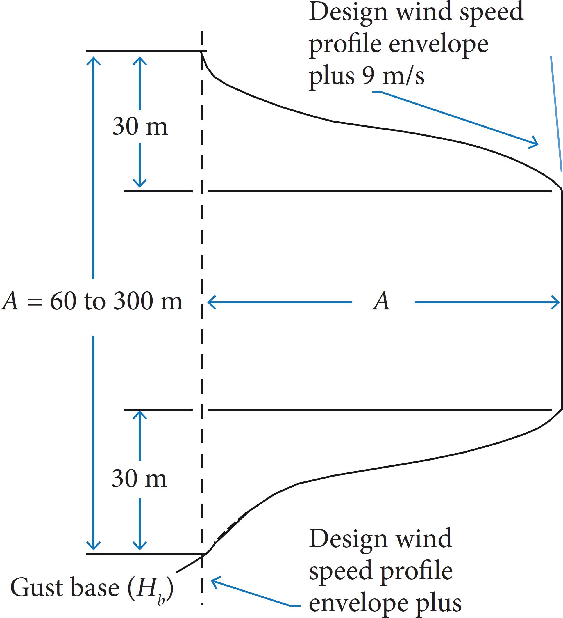
Classical NASA 9-m/s discrete gust model. Since one cannot monitor short (gust) wavelengths, this gust model was derived as a direct vehicle design requirement to help establish the design of vehicle structure and control systems. This was intended to produce a minimum risk flight capability taking into account, from a systems engineering point of view, the aerodynamic and other uncertainties. It was originally taken from aircraft gust studies.
The original quasi-square wave gust model was developed by NASA in 1963 and has an amplitude of 9 m/s, with a gust width from 60 to 300 m, as shown in Fig 2. It is used by NASA for elastic body loads and is based on established methods (and aircraft turbulence data) that are included in MIL-F-8785B.40 When used in conjunction with the synthetic wind and wind shear model for Shuttle ascent design, the design gust model amplitude is reduced to 7.65 m/s (0.85 of its value). However, although small, it is not known exactly what probability of occurrence should be attached to this gust model. Also, there is no relationship between gust magnitude and gust half width (between 30 and 150 m). Inferred evidence from aircraft vertical gust measurements to support application of the 9 m/s discrete gusts with half-widths as small as 30 m.
-
Improved discrete gust model. The improved discrete gust model was introduced in 1997 (Smith and Adelfang 1998Smith OE, Adelfang SI (1998) A compendium of wind statistics and models for the NASA space shuttle and other aerospace vehicle programs. (CR-1998-208859). NASA Technical Report.), and is also established with methods originally developed for MIL-F-8785B (Department of Defense 1969). However, it is a gust model that includes variation of gust amplitude (magnitude) with gust width (half width). It is also a function of altitude and reflects the severity of turbulence.
Power Spectral. The power spectral approach provides a more realistic description of the continuous nature of atmospheric turbulence on a vehicle. The turbulence power spectra are used as a forcing function, and the response spectra are obtained through use of the vehicle frequency response function. The vehicle frequency response function can be calculated numerically for a range of sinusoidal gust frequencies and used with any desired turbulence spectrum. Spectral methods have been employed to specify the characteristics of small-scale motions. Spectra of detailed wind profiles (scalar, zonal, and meridional) can be computed (with and without filtering) for engineering design studies. Energy (variance) of the small-scale motions is not homogenous; i.e., it is not constant with altitude. The energy content over limited latitude intervals and for limited frequency bands may be much larger than that represented by the average spectra (50th percentile). The range of energy content is given approximately by the 1st and 99th percentile envelopes. This range of energy should be kept in mind when employing spectra of small-scale motions to interpret the significance of vehicle responses.
-
Power Spectrum Analysis. The determination of aerodynamic loads by power spectrum analysis is restricted to linear time-invariant differential systems with stationary input processes. It is evident that the flight of the launch vehicle through the atmosphere is a strongly nonstationary process. Not only does the system parameters vary due to the rapid propellant consumption but also the atmospheric flight conditions. The difficulty can partly be circumvented by restricting the analysis to small time intervals and assuming the spatial characteristics of the wind process to have local stationarity. The latter condition is approximately satisfied for the wind turbulence. A widely used power spectrum model for the turbulence is that of H. Press, containing the scale of turbulence (L) and the variance of the turbulence (σt). At altitudes below 50,000 ft, this power spectrum seems to be an acceptable model for the atmospheric turbulence, with the scale of turbulence ranging from 500 to 1,000 m, depending on the altitude and the variance of the turbulence from 1 to 4 m2/s2. Other possible forms of power spectra can be used. The Press turbulence model approximates only the variance of wind but poorly approximates that of the wind shear (wind shear variance becomes infinite). This presents a problem in calculating the number of exceedances (becoming infinite) for a vehicle with angle of attack feedback. This difficulty can be avoided by using a power spectrum model that conforms to specified wind and wind shear variances.
Sometimes it is advantageous in statistical simulation studies to construct a random signal as the output of a dynamical system excited by an independent Gaussian stochastic process - white noise, since white noise is characterized by a constant power spectrum.
Deterministic vehicle dynamic analysis involving wind and atmospheric parameters.
Aerodynamic Forces and Moments. In addition to the gravity force, the atmosphere exerts pressure on the launch vehicle, resulting in aerodynamic forces and moments. Various models of the atmosphere (Standard and Range Reference Atmospheres) have been used, which should provide acceptable accuracy in determining aerodynamic loads for any launch site. For axially symmetric vehicles, the absolute angle of attack is sufficient in calculating aerodynamic forces and moments for a boost trajectory. It is desirable to have the capability to break the launch vehicle down into several aerodynamic sections in order to incorporate the effects of gradual gust penetration. The buoyancy due to the air displaced by large Saturn-type vehicles is » 0.1% of the total thrust and can be neglected.
The NASA MSFC Global Reference Atmospheric Model (Leslie and Justus 2008Leslie FW, Justus CG (2008) The NASA MSFC Earth global reference atmospheric model - 2007 Version. (TM-2008-215581). NASA Technical Memorandum.) is a worldwide model from surface through orbital altitudes that can be used to calculate monthly mean atmospheric thermodynamic (and wind) properties, and the variability of these properties about the monthly mean, for any global location or along any given trajectory. A schematic illustration of the atmospheric regions within the GRAM-07 program, and sources for the models and data on which the mean monthly GRAM-07 values are based is presented in Fig. 3.
Schematic summary of the atmospheric regions versus altitude in the GRAM-07 program, and sources for the models/data on which the mean monthly GRAM-07 values are based (Johnson, 2008Johnson DL (2008) Terrestrial environment (climatic) criteria guidelines for use in aerospace vehicle development, 2008 Revision. (TM-2008-215633). NASA Technical Memorandum.).
Thrust. Thrust for a given propellant and rocket motor geometry depends not only on the mass flow rate and effective exhaust velocity but also on the ambient atmospheric pressure and thus the altitude of the vehicle. Since the atmospheric pressure is the only thrust parameter that goes through significant changes during booster flight, the use of a single-entry table is sufficient for the calculation of the thrust force. The key is to specify the reference atmosphere that is used for this input, i.e. US76, etc.
Atmospheric moisture has also been a parameter to consider in the design and in calculating the performance of various vehicle engines, such as in the National Aero Space Plane (NASP) program (Johnson 1994Johnson DL (1994) National aerospace plane (NASP) X-30 natural environment requirements document (Rev. 1.0). (TM-108451). NASA Technical Memorandum.).
Engine Inertia. The swivel engines, in responding to commands from the G&C computer, can be deflected at substantial angular accelerations, which gives rise to inertia forces and moments caused by the engine inertia. Although the engine inertia effect can be of importance for high wind shear conditions, it is often overshadowed by lag effects of servo-actuator engine compliance and shaping networks.
Statistical Terrestrial Environment Mission Analysis. Most standard statistical summaries of terrestrial environment variables are tabulated for single variables or a combination of a few variables, such as cloud ceilings and visibilities, and they require parametric statistical summaries. Interest is not only in the probability of each of the several terrestrial environment variables taken separately, but also in the probability that at least one of several variables will be of concern for a launch vehicle’s particular operational phase or several phases. For example, if there is a launch constraint due to several terrestrial environment parameters of which any one will constitute a no-go condition, then the probability of interest is the probability that any one of the constraints will occur. The purpose of a statistical terrestrial environment mission analysis is to address the following questions relative to assumed or assigned natural environmental constraints for the operational phases of a new launch vehicle:
-
What is the probability that the designated natural environmental constraints will (will not) occur during a particular monthly reference period?
-
What is the probability that the designated natural environmental constraints will (will not) occur for N consecutive days at a particular time of day during a monthly reference period?
-
Once the designated natural environmental constraint has occurred (has not occurred) for 1, 2, 3, … N consecutive days at a particular time of day, what is the probability that the given constraints will continue for N additional days?
Valid answers to these questions have practical applications to any new launch vehicle program development in the following LV mission interrelated areas:
-
Establishing terrestrial environment design criteria.
-
Operational planning.
-
Establishing launch and flight operational rules.
-
Program decisions on cost-trade assessments.
CONCLUSION
Terrestrial and space environments associated with the design and development of new launch or space vehicles are presented here and in the previous two JATM papers. These papers also address the basis for the NE guidelines presented, the interpretation of the guidelines, and application to the development of launch/space vehicle design requirements. Any new launch vehicle program or project should consider, early in its development stages, the NE guideline applications suggested in this paper. A better understanding and application of the NE and its effect on launch vehicles will enable engineering and program management to more effectively minimize program risks and costs, optimize design quality, and successfully achieve mission objectives.
ACKNOWLEDGMENTS
The authors wish to thank Dr. Stanley I Adelfang, and (the late) Orvel E Smith (both of Stanley Associates) for their most valuable technical and historical terrestrial environment contributions and support. Also to Dr. B.J. Anderson and Dr. Robert E. Smith (both NASA retired) for their space environment contributions.
REFERENCES
- Adelfang SI (1999) User’s guide for monthly vector wind profile model. (CR-1999-209759). NASA Technical Report.
- Adelfang SI, Smith OE, Batts GW (1994) Ascent wind model for launch vehicle design. J Spacecraft and Rockets 31(3):502-508. https://doi.org/10.2514/3.26467
» https://doi.org/10.2514/3.26467 - Bowman BR, Tobiska WK, Marcos FA, Valladares C (2008) The JB2006 empirical thermosphere density model. Journal of Atmospheric and Solar-Terrestrial Physics 70(5):774-793. https://doi.org/10.1016/j.jastp.2007.10.002
» https://doi.org/10.1016/j.jastp.2007.10.002 - Department of Defense (1969) Military Specification Flying Qualities of Piloted Airplanes. (MILF-8785B). US Airforce Technical Report.
- Geissler ED (1970) Wind effects on launch vehicles. Slough: Technivision Services.
- Leslie FW, Justus CG (2008) The NASA MSFC Earth global reference atmospheric model - 2007 Version. (TM-2008-215581). NASA Technical Memorandum.
- Johnson DL (1994) National aerospace plane (NASP) X-30 natural environment requirements document (Rev. 1.0). (TM-108451). NASA Technical Memorandum.
- Johnson DL (2008) Terrestrial environment (climatic) criteria guidelines for use in aerospace vehicle development, 2008 Revision. (TM-2008-215633). NASA Technical Memorandum.
- Johnson DL; Vaughan WW (2019) The Role of Terrestrial and Space Environments in Launch Vehicle Development. J Aerosp Technol Manag, 11: e4719. https://doi.org/10.5028/jatm.v11.1088
» https://doi.org/10.5028/jatm.v11.1088 - Johnson DL; Vaughan WW (2020) Key Terrestrial And Space Environment Sources. J Aerosp Technol Manag, 12: e0120. https://doi.org/10.5028/jatm.v12.1089
» https://doi.org/10.5028/jatm.v12.1089 - [NASA] National Aeronautics and Space Administration (n.d.) NASA space vehicle design criteria SP-8000. NASA. http://library.msfc.nasa.gov/cgi-bin/lsp8000>
» http://library.msfc.nasa.gov/cgi-bin/lsp8000 - Pearson SD, Vaughan WW, Batts CW, Jasper GL (1996) Importance of the natural terrestrial environment with regard to advanced launch vehicle design and development. (TM-108511). NASA Technical Memorandum.
- Smith OE (1976) Vector wind and vector wind shear models 0 to 27km altitude for Cape Kennedy, Florida and at Vandenberg AFB, California. (TM-X-73319). NASA Technical Report.
- Smith OE, Adelfang SI (1998) A compendium of wind statistics and models for the NASA space shuttle and other aerospace vehicle programs. (CR-1998-208859). NASA Technical Report.
Edited by
Publication Dates
-
Publication in this collection
17 Jan 2020 -
Date of issue
2020
History
-
Received
31 Jan 2019 -
Accepted
26 Mar 2019